MI VIF API
REVISION HISTORY
| Revision No. | Description |
Date |
|---|---|---|
| 3.0 | 12/04/2020 | |
| 3.1 | 07/16/2021 | |
| 3.2 | 08/25/2021 | |
| 3.3 | 12/22/2021 | |
| 3.4 | 02/17/2022 | |
| 3.5 | 03/21/2022 | |
| 3.6 | 07/08/2022 | |
| 3.7 | 08/01/2024 |
1. OVERVIEW
1.1. Module description
Video input (VIF) enables video input device, video input channel, binding video input channel and other functions.
1.2. Flow chart
1.2.1. Tiramisu flow

Note:
-
There are only 8 Devices and 8 Pipes available in 16 Devices.
-
Four sensors of Mipi interface are used respectively:
linear mode: dev0/dev4/dev8/dev12
hdr frame mode: dev0/dev1, dev4/dev5, dev8/dev9, dev12/dev13
hdr reatlime mode: dev0/dev1
-
Two sensors of BT656 interface are used respectively: sensor pad0/2.
-
Each device has only one channel ID0, which can be used when binding to the backend through MI_SYS.
PortId Input Pixel Output Pixel Crop Scaling Output Format 0 Input according to sensor format 1. Input according to sensor format;
2. Convert YUV422 format to 12bit bayer format for output.No support No support 1. Dram output;
2. One Device supports sensor format realtime output to MI_ISP, DeviceId is not limited.
3. Another Device supports YUV422 format realtime output to MI_SCL, DeviceId is not limited.1 Only support YUV422 format input Only support 12bit bayer format output Support Only support scaling down, when scaling down height, the maximum width is 960. Only support Dram output.
1.2.2. Muffin flow

Note:
-
Up to 32 Devices and 32 Pipes available.
-
8 sensors of Mipi interface are used in the following:
linear mode: dev0/dev4/dev8/dev12, dev16/dev20/dev24/dev28
hdr frame mode: dev0/dev1, dev4/dev5, dev8/dev9, dev12/dev13, dev16/dev17, dev20/dev21, dev24/dev25, dev28/dev29
hdr reatlime mode: dev0/dev1, dev16/dev17
-
8 sensors of BT656 interface are used in pad0/pad2/pad1/pad3/pad4/pad6/pad5/pad7
-
4 sensors of BT1120 interface are used in pad0/pad1/pad4/pad5
-
4 sensors of Lvds interface are used in the following:
Linear mode: dev0/dev8, dev/16/dev24
Hdr frame mode: dev0/dev1, dev8/dev9, dev16/dev17, dev24/dev25
Hdr realitme mode: dev0/dev1, dev16/dev17
-
Each device has only one channel ID0, which can be used when binding to the backend through MI_SYS.
PortId Input Pixel Output Pixel Crop scaling Output Format 0 Input according to sensor format 1. Output according to sensor format;
2. Convert YUV422 format to 12bit bayer format for outputNot support Not support 1. Dram Output.
2. Dev0 Supports Bayer realtime to MI_ISP Dev0, Dev16 supports Bayer realtime to MI_ISP Dev1
3. Dev8 supports YUV422 realtime to MI_SCL Dev2, Dev24 supports YUV422 realtime to MI_SCL Dev6
1.2.3. Mochi flow

Note:
-
Up to 16 Devices and 16 Pipes available.
-
4 sensors of Mipi(YUV) interface are used in pad0/pad2/pad1/pad3, do not support HDR, like BT656, 1pad supports 4 dev output the most.
-
4 sensors of BT656 interface are used in pad0/pad2/pad1/pad3.
-
2 sensors of BT1120 interface are used in pad0/pad1.
-
Each device has only one channel ID0, which can be used when binding to the backend through MI_SYS.
PortId Input Pixel Output Pixel Crop scaling Output Format 0 Only support YUV422 format input Only support YUV422 format output Not support Not support 1. Dram Output.
2. Dev0 supports yuv realtime to MI_ISP Dev0.
1.2.4. Maruko

Note:
-
Up to 9 Devices and 4 Pipes available.
-
2 sensors of Mipi(YUV) interface are used in pad0/pad2, 1 pad supports 4 dev output the most. Pad0 supports 4lane or can be disassembled into 2 + 2 Lane (pad0 + Pad2).
-
BT656 only supports sensor Pad1 and only one sensor signal.
-
Not support BT1120.
-
Each device has only one channel ID0, which can be used when binding to the backend through MI_SYS.
PortId Input Pixel Output Pixel Crop scaling Output Format 0 Input according to sensor format output according to sensor format Not support Not support 1. Dram Output.
2. Dev0 Support Yuv realtime to MI_ISP Dev0.
3. Another Device support YUV422 format realtime output to MI_SCL, DeviceId is not limited.
1.3. Keyword
-
Group
A sensor pad may mix multiple signals, so a sensor pad needs a corresponding group to receive.
-
Dev
A device that processes a single signal in a group.
-
Port
Output port on Dev.
-
Pipe
Pipe is VIF internal path for data stream, distributed by all device, determines the maximum number of channels that VIF can output at the same time.
-
DI mode
De interlacing function to synthesize 2 fields into one field.
2. API REFERENCE
This function module provides the following API:
| API Name | Function |
|---|---|
| MI_VIF_CreateDevGroup | Create a Group corresponding to Device |
| MI_VIF_DestroyDevGroup | Destroy Group |
| MI_VIF_GetDevGroupAttr | Get Group attributes |
| MI_VIF_SetDevAttr | Set device attribute |
| MI_VIF_GetDevAttr | Get device attribute |
| MI_VIF_EnableDev | Enable device |
| MI_VIF_DisableDev | Disable device |
| MI_VIF_GetDevStatus | Get device status |
| MI_VIF_SetOutputPortAttr | Set output port attribute |
| MI_VIF_GetOutputPortAttr | Get output port attribute |
| MI_VIF_EnableOutputPort | Enable output port |
| MI_VIF_DisableOutputPort | Disable output port |
| MI_VIF_Query | Query VIF channel port interrupt counts, average frame rate, etc. |
| MI_VIF_CallBackTask_Register | Register callback interface with VIF |
| MI_VIF_CallBackTask_UnRegister | Unregister callback interface with VIF |
2.1. MI_VIF_CreateDevGroup
-
Description
Create a Group corresponding to Device
-
Syntax
MI_S32 MI_VIF_CreateDevGroup(MI_VIF_GROUP GroupId, MI_VIF_GroupAttr_t *pstGroupAttr)
-
Parameters
Parameter Name Description Input/Output GroupId Group ID Input pstGroupAttr Group attributes, static attributes. Input -
Return Value
-
MI_SUCCESS(0): Successful
-
Non-zero: Failed, see error code for details
-
-
Dependence
-
Header: mi_vif_datatype.h, mi_vif.h
-
Library: libmi_vif.a
-
-
Note
-
When MI VIF and back-end module have both real-time and FrameMode connections, such as ISP Bayer Realitme, SCL Dev2 YUV Realitme, and other Devs have Frame mode connections, priority should be given to create DevGroup with real-time connection and bind back-end module.
-
Before Creating DevGroup, make sure that the sensor flows out successfully. That is, if you use our Mi sensor, you need to ensure MI_SNR_Enable. If you use your user sensor, you need to ensure that the user's own sensor has been initialized.
-
Group Id Device Id 0 Device0~3 1 Device4~7 2 Device8~11 3 Device12~15 4 Device16~19 5 Device20~23 6 Device24~27 7 Device28~31
-
-
Example
#define ST_MAX_VIF_DEV_PERGROUP (4)
#define ST_MAX_VIF_OUTPORT_NUM (2)
MI_VIF initialization process:
MI_S32 ST_VifModuleInit(MI_VIF_GROUP groupId)
{
    MI_VIF_DEV vifDev =0;
    MI_VIF_PORT vifPort = 0;
    MI_SNR_PADID SnrPadId = 0;
    MI_U32 u32PlaneId = 0;
    MI_U16 vifDevIdPerGroup=0;

    MI_SNR_PADInfo_t  stPad0Info;
    MI_SNR_PlaneInfo_t stSnrPlane0Info;
    memset(&stPad0Info, 0x0, sizeof(MI_SNR_PADInfo_t));
    memset(&stSnrPlane0Info, 0x0, sizeof(MI_SNR_PlaneInfo_t));

    MI_VIF_GroupAttr_t stGroupAttr;
    memset(&stGroupAttr, 0x0, sizeof(MI_VIF_GroupAttr_t));

    STCHECKRESULT(MI_SNR_GetPadInfo(SnrPadId, &stPad0Info));
    STCHECKRESULT(MI_SNR_GetPlaneInfo(SnrPadId, u32PlaneId, &stSnrPlane0Info));

    stGroupAttr.eIntfMode = E_MI_VIF_MODE_MIPI;
    stGroupAttr.eWorkMode = E_MI_VIF_WORK_MODE_1MULTIPLEX;
    stGroupAttr.eHDRType = E_MI_VIF_HDR_TYPE_OFF;
    if(stGroupAttr.eIntfMode == E_MI_VIF_MODE_BT656)
        stGroupAttr.eClkEdge = (MI_VIF_ClkEdge_e)stPad0Info.unIntfAttr.stBt656Attr.eClkEdge;
    else
        stGroupAttr.eClkEdge = E_MI_VIF_CLK_EDGE_DOUBLE;

    STCHECKRESULT(MI_VIF_CreateDevGroup(groupId, &stGroupAttr));

    for(vifDevIdPerGroup=0; vifDevIdPerGroup< ST_MAX_VIF_DEV_PERGROUP; vifDevIdPerGroup++)
    {
        MI_VIF_DevAttr_t stVifDevAttr;
        memset(&stVifDevAttr, 0x0, sizeof(MI_VIF_DevAttr_t));

        vifDev = groupId*ST_MAX_VIF_DEV_PERGROUP+vifDevIdPerGroup;
        stVifDevAttr.stInputRect.u16X = stSnrPlane0Info.stCapRect.u16X;
        stVifDevAttr.stInputRect.u16Y = stSnrPlane0Info.stCapRect.u16Y;
        stVifDevAttr.stInputRect.u16Width = stSnrPlane0Info.stCapRect.u16Width;
        stVifDevAttr.stInputRect.u16Height = stSnrPlane0Info.stCapRect.u16Height;
        if(stSnrPlane0Info.eBayerId = E_MI_SYS_PIXEL_BAYERID_MAX)
        {
            stVifDevAttr.eInputPixel = stSnrPlane0Info.ePixel;
        }
        else
            stVifDevAttr.eInputPixel = (MI_SYS_PixelFormat_e)RGB_BAYER_PIXEL(stSnrPlane0Info.ePixPrecision, stSnrPlane0Info.eBayerId);

        printf("setchnportattr (%d,%d,%d,%d) \n", stVifDevAttr.stInputRect.u16X, stVifDevAttr.stInputRect.u16Y, stVifDevAttr.stInputRect.u16Width, stVifDevAttr.stInputRect.u16Height);
        STCHECKRESULT(MI_VIF_SetDevAttr(vifDev, &stVifDevAttr));
        STCHECKRESULT(MI_VIF_EnableDev(vifDev));

        for(vifPort=0; vifPort< ST_MAX_VIF_OUTPORT_NUM; vifPort++)
        {
            MI_VIF_OutputPortAttr_t stVifPortInfo;
            memset(&stVifPortInfo, 0, sizeof(MI_VIF_OutputPortAttr_t));

            stVifPortInfo.stCapRect.u16X = stSnrPlane0Info.stCapRect.u16X;
            stVifPortInfo.stCapRect.u16Y = stSnrPlane0Info.stCapRect.u16Y;
            stVifPortInfo.stCapRect.u16Width =  stSnrPlane0Info.stCapRect.u16Width;
            stVifPortInfo.stCapRect.u16Height = stSnrPlane0Info.stCapRect.u16Height;
            stVifPortInfo.stDestSize.u16Width = stSnrPlane0Info.stCapRect.u16Width;
            stVifPortInfo.stDestSize.u16Height = stSnrPlane0Info.stCapRect.u16Height;
            printf("sensor bayerid %d, bit mode %d \n", stSnrPlane0Info.eBayerId, stSnrPlane0Info.ePixPrecision);
            if(stSnrPlane0Info.eBayerId = E_MI_SYS_PIXEL_BAYERID_MAX)
            {
                stVifPortInfo.ePixFormat = stSnrPlane0Info.ePixel;
            }
            else
                stVifPortInfo.ePixFormat = (MI_SYS_PixelFormat_e)RGB_BAYER_PIXEL(stSnrPlane0Info.ePixPrecision, stSnrPlane0Info.eBayerId);
            stVifPortInfo.eFrameRate = E_MI_VIF_FRAMERATE_FULL;

            STCHECKRESULT(MI_VIF_SetOutputPortAttr(vifDev, vifPort, &stVifPortInfo));
            STCHECKRESULT(MI_VIF_EnableOutputPort(vifDev, vifPort));
        }
    }
    return MI_SUCCESS;
}
MI_VIF deinitialization process:
MI_S32 ST_VifModuleUnInit(MI_VIF_GROUP groupId) { MI_VIF_DEV vifDev = 0; MI_VIF_PORT vifPort=0; MI_U16 vifDevIdPerGroup=0; for(vifDevIdPerGroup=0; vifDevIdPerGroup< ST_MAX_VIF_DEV_PERGROUP; vifDevIdPerGroup++) { vifDev = groupId*ST_MAX_VIF_DEV_PERGROUP+vifDevIdPerGroup; for(vifPort=0; vifPort< ST_MAX_VIF_OUTPORT_NUM; vifPort++) { STCHECKRESULT(MI_VIF_DisableOutputPort(vifDev, vifPort)); } STCHECKRESULT(MI_VIF_DisableDev(vifDev)); } STCHECKRESULT(MI_VIF_DestroyDevGroup(groupId)); return MI_SUCCESS; } -
Related APIs
2.2. MI_VIF_DestroyDevGroup
-
Description
Destroy the group corresponding to the device.
-
Syntax
MI_S32 MI_VIF_DestroyDevGroup(MI_VIF_GROUP GroupId)
-
Parameters
Parameter Name Description Input/Output GroupId Group ID Input -
Return Value
-
MI_SUCCESS(0): Successful
-
Non-zero: Failed, see error code for details
-
-
Dependence
-
Header: mi_vif_datatype.h, mi_vif.h
-
Library: libmi_vif.a
-
-
Note
At first, use MI_VIF_DisableOutputPort to disable all the output ports on device, the use MI_VIF_DisableDev to disable all the devices on group.
-
Example
See the example of MI_VIF_CreateDevGroup.
-
Related APIs
2.3. MI_VIF_GetDevGroupAttr
-
Description
Get Group attributes.
-
Syntax
MI_S32 MI_VIF_GetDevGroupAttr(MI_VIF_GROUP GroupId, MI_VIF_GroupAttr_t *pstGroupAttr)
-
Parameters
Parameter Name Description Input/Output GroupId Group ID Input pstGroupAttr Group attributes Output -
Return Value
-
MI_SUCCESS(0): Successful
-
Non-zero: Failed, see error code for details
-
-
Dependence
-
Header: mi_vif_datatype.h, mi_vif.h
-
Library: libmi_vif.a
-
-
Related APIs
2.4. MI_VIF_SetDevAttr
-
Description
Set VIF device attributes.
-
Syntax
MI_S32 MI_VIF_SetDevAttr(MI_VIF_DEV DevId, MI_VIF_DevAttr_t *pstDevAttr)
-
Parameters
Parameter Name Description Input/Output DevId VIF device ID Input pstDevAttr VIF device attribute pointer, static attribute. Input -
Return Value
-
MI_SUCCESS(0): Successful
-
Non-zero: Failed, see error code for details
-
-
Dependence
-
Header: mi_vif_datatype.h, mi_vif.h
-
Library: libmi_vif.a
-
-
Note
-
Make sure that the VIF device is disabled before calling. If the VIF device is enabled, you can use MI_VIF_DisableDev to disable it.
-
pstDevAttr is mainly used to configure the video input format of the specified VIF device.
-
eInputPixel only supports YUV422_YUYV/YVYU/UYVY/VYUY and bayer formats, please refer to chapter 1.2 for details, and set according to chip specifications.
-
-
Example
See the example of MI_VIF_CreateDevGroup.
-
Related APIs
2.5. MI_VIF_GetDevAttr
-
Description
Get VIF device attribute.
-
Syntax
MI_S32 MI_VIF_GetDevAttr(MI_VIF_DEV DevId, MI_VIF_DevAttr_t *pstDevAttr)
-
Parameters
Parameter Name Description Input/Output DevId VIF device ID Input pstDevAttr VIF device attribute pointer. Output -
Return Value
-
MI_SUCCESS(0): Successful
-
Non-zero: Failed, see error code for details
-
-
Dependence
-
Header: mi_vif_datatype.h, mi_vif.h
-
Library: libmi_vif.a
-
-
Related APIs
2.6. MI_VIF_EnableDev
-
Description
Enable VIF device.
-
Syntax
MI_S32 MI_VIF_EnableDev(MI_VIF_DEV DevId);
-
Parameters
Parameter Name Description Input/Output DevId VIF device ID Input -
Return Value
-
MI_SUCCESS(0): Successful
-
Non-zero: Failed, see error code for details
-
-
Dependence
-
Header: mi_vif_datatype.h, mi_vif.h
-
Library: libmi_vif.a
-
-
Note
-
Enable must be after device attribute have be configured, or fail will be returned
-
Calling again is available, fail will not be returned.
-
-
Example
Please refer to MI_VIF_SetDevAttr.
-
Related APIs
2.7. MI_VIF_DisableDev
-
Description
Disable VIF device.
-
Syntax
MI_S32 MI_VIF_DisableDev(MI_VIF_DEV DevId);
-
Parameters
Parameter Name Description Input/Output DevId VIF device ID Input -
Return Value
-
MI_SUCCESS(0): Successful
-
Non-zero: Failed, see error code for details
-
-
Dependence
-
Header: mi_vif_datatype.h, mi_vif.h
-
Library: libmi_vif.a
-
-
Note
-
Disable all the output ports on device before disable the VIF device.
-
Calling again is available, fail will not be returned.
-
-
Example
See the example of MI_VIF_CreateDevGroup
-
Related APIs
2.8. MI_VIF_GetDevStatus
-
Description
Get device status.
-
Syntax
MI_S32 MI_VIF_GetDevStatus(MI_VIF_DEV DevId, MI_VIF_DevStatus_t *pstVifDevStatus)
-
Parameters
Parameter Description Input/Output DevId VIF device ID Input pstVifDevStatus Device status Output -
Return Value
-
MI_SUCCESS(0): Successful
-
Non-zero: Failed, see error code for details
-
-
Dependence
-
Header: mi_vif_datatype.h, mi_vif.h
-
Library: libmi_vif.a
-
2.9. MI_VIF_SetOutputPortAttr
-
Description
Set VIF channel Output port attributes.·
-
Syntax
MI_S32 MI_VIF_SetOutputPortAttr(MI_VIF_DEV DevId, MI_VIF_PORT PortId, MI_VIF_OutputPortAttr_t *pstAttr);
-
Parameters
Parameter Name Description Input/Output DevId VIF device ID Input PortId Port ID Input pstAttr VIF device port attribute pointer Input -
Return Value
-
MI_SUCCESS(0): Successful
-
Non-zero: Failed, see error code for details
-
-
Dependence
-
Header: mi_vif_datatype.h, mi_vif.h
-
Library: libmi_vif.a
-
-
Note
-
MI_VIF_SetOutputPortAttr is used for setting port attribute in default, such as CapSize, DestSize, FrameRate, ect.
-
Port 0 does not support crop and scaling, so cap and dest size must be equal to input size in MI_VIF_SetDevAttr.
-
The input of port1 only supports YUV format, so only YUVsensor can use port1, which supports crop and scaling down, and the output only supports 12bit bayer format.
-
When Port1 height is scaling down, the maximum output width is 960.
-
Tiramisu/Muffin/Mochi series chips: eFrameRate setting is not supported.
-
Tiramisu/Muffin series chips: port0 supports output 12-bit Bayer format, which can be sent to MI_ISP for 3DNR.
-
Mochi series chip: supports output YUV422 format, which can be sent to MI_ISP for 3DNR.
Chip Compress support pixel Support compress mode Note Tiramisu Bayer 10/12bit E_MI_SYS_COMPRESS_MODE_TO_8BIT None Muffin Bayer 10/12bit E_MI_SYS_COMPRESS_MODE_TO_8BIT None Mochi YUV422 UYVY E_MI_SYS_COMPRESS_MODE_TO_6BIT
E_MI_SYS_COMPRESS_MODE_SFBC0DI mode does not support SFBC0 compress mode. Maruko Bayer 10/12bit E_MI_SYS_COMPRESS_MODE_TO_8BIT None
-
-
Example
See the example of MI_VIF_CreateDevGroup.
-
Related APIs
2.10. MI_VIF_GetOutputPortAttr
-
Description
Get VIF channel Output port attributes.
-
Syntax
MI_S32 MI_VIF_GetOutputPortAttr(MI_VIF_DEV DevId, MI_VIF_PORT PortId, MI_VIF_OutputPortAttr_t *pstAttr)
-
Parameters
Parameter Name Description Input/Output DevId VIF device ID Input PortId Port ID Input pstAttr VIF device port attribute pointer Output -
Return Value
-
MI_SUCCESS(0): Successful
-
Non-zero: Failed, see error code for details
-
-
Dependence
-
Header: mi_vif_datatype.h, mi_vif.h
-
Library: libmi_vif.a
-
-
Related APIs
2.11. MI_VIF_EnableOutputPort
-
Description
Enable VIF Output port.
-
Syntax
MI_S32 MI_VIF_EnableOutputPort(MI_VIF_DEV DevId, MI_VIF_PORT PortId)
-
Parameters
Parameter Name Description Input/Output DevId VIF device ID Input PortId Port ID Input -
Return Value
-
MI_SUCCESS(0): Successful
-
Non-zero: Failed, see error code for details
-
-
Dependence
-
Header: mi_vif_datatype.h, mi_vif.h
-
Library: libmi_vif.a
-
-
Note
-
The channel attributes must be set first, and the VIF device bound channel must be enabled.
-
The VIF channel can be enabled repeatedly without returning failure.
-
-
Example
See the example of MI_VIF_SetDevAttr.
-
Related APIs
2.12. MI_VIF_DisableOutputPort
-
Description
Disable VIF Output port.
-
Syntax
MI_S32 MI_VIF_DisableOutputPort(MI_VIF_DEV DevId, MI_VIF_PORT PortId)
-
Parameters
Parameter Name Description Input/Output DevId VIF device ID Input PortId Port ID Input -
Return Value
-
MI_SUCCESS(0): Successful
-
Non-zero: Failed, see error code for details
-
-
Dependence
-
Header: mi_vif_datatype.h, mi_vif.h
-
Library: libmi_vif.a
-
-
Note
-
The VIF channel port stops collecting video input data after being disabled. And if the backend has been bound, the backend will no longer receive video images.
-
The VIF channel can be disabled repeatedly without returning failure.
-
-
Example
See the example of MI_VIF_CreateDevGroup.
-
Related APIs
2.13. MI_VIF_Query
-
Description
Query VIF channel port interrupt counts, average frame rate, etc.
-
Syntax
MI_S32 MI_VIF_Query(MI_VIF_DEV DevId, MI_VIF_PORT PortId, MI_VIF_DevPortStat_t *pstStat)
-
Parameters
Parameter Name Description Input/Output DevId VIF device ID Input PortId Port ID Input pstStat Channel information structure pointer. Output -
Return Value
-
MI_SUCCESS(0): Successful
-
Non-zero: Failed, see error code for details
-
-
Dependence
-
Header: mi_vif_datatype.h, mi_vif.h
-
Library: libmi_vif.a
-
-
Note
-
This API can be used to query interrupt counts, channel enable/disable status, interrupt loss counts, VB fail counts, height/width of image
-
Frame rate got via this API is average frame rate over 1 second, VIF could calculate average frame rate every second, the precision of this value is not exact
-
User could query interrupt loss counts via this API. If this loss counts increase at all time, it meant VIF is abnormal.
-
This interface is only supported by chips after Tiramisu.
-
2.14. MI_VIF_CallBackTask_Register
-
Description
Register callback interface with VIF
-
Syntax
MI_S32 MI_VIF_CallBackTask_Register(MI_VIF_DEV DevId, MI_VIF_CallBackParam_t *pstCallBackParam);
-
Parameters
Parameter Name Description Input/Output DevId VIF device ID Input pstCallBackParam Arguments Input -
Return Value
-
MI_SUCCESS(0): Successful
-
Non-zero: Failed, see error code for details
-
-
Dependence
-
Header: mi_vif_datatype.h, mi_vif.h
-
Library: libmi_vif.a
-
-
Note
-
Currently, this interface only supports kernel mode calls
-
This interface must be called in pair with MI_VIF_CallBackTask_UnRegister
-
This feature is not supported in the current version
-
-
Example
MI_S32 _mi_vif_framestart1(MI_U64 u64Data) { DBG_ERR("DATA %llu \n", u64Data); return 0; } MI_S32 _mi_vif_framestart2(MI_U64 u64Data) { DBG_ERR("DATA %llu \n", u64Data); return 0; } static MS_S32 _mi_vif_testRegVifCallback(void) { MI_VIF_CallBackParam_t stCallBackParam1; MI_VIF_CallBackParam_t stCallBackParam2; MI_VIF_DEV u32DevId = 0; memset(&stCallBackParam1, 0x0, sizeof(MI_VIF_CallBackParam_t)); memset(&stCallBackParam2, 0x0, sizeof(MI_VIF_CallBackParam_t)); stCallBackParam1.eCallBackMode = E_MI_VIF_CALLBACK_ISR; stCallBackParam1.eIrqType = E_MI_VIF_IRQ_FRAMESTART; stCallBackParam1.pfnCallBackFunc = _mi_vif_framestart1; stCallBackParam1.u64Data = 11; MI_VIF_CallBackTask_Register(u32DevId,&stCallBackParam1); stCallBackParam2.eCallBackMode = E_MI_VIF_CALLBACK_ISR; stCallBackParam2.eIrqType = E_MI_VIF_IRQ_FRAMESTART; stCallBackParam2.pfnCallBackFunc = _mi_vif_framestart2; stCallBackParam2.u64Data = 22; MI_VIF_CallBackTask_Register(u32DevId,&stCallBackParam2); return 0; } static MS_S32 _mi_vif_testUnRegVifCallback(void) { MI_VIF_CallBackParam_t stCallBackParam1; MI_VIF_CallBackParam_t stCallBackParam2; MI_VIF_DEV u32DevId = 0; memset(&stCallBackParam1, 0x0, sizeof(MI_VIF_CallBackParam_t)); memset(&stCallBackParam1, 0x0, sizeof(MI_VIF_CallBackParam_t)); stCallBackParam1.eCallBackMode = E_MI_VIF_CALLBACK_ISR; stCallBackParam1.eIrqType = E_MI_VIF_IRQ_FRAMESTART; stCallBackParam1.pfnCallBackFunc = _mi_vif_framestart1; stCallBackParam1.u64Data = 33; MI_VIF_CallBackTask_UnRegister(u32DevId,&stCallBackParam1); stCallBackParam2.eCallBackMode = E_MI_VIF_CALLBACK_ISR; stCallBackParam2.eIrqType = E_MI_VIF_IRQ_FRAMESTART; stCallBackParam2.pfnCallBackFunc = _mi_vif_framestart2; stCallBackParam2.u64Data = 44; MI_VIF_CallBackTask_UnRegister(u32DevId,&stCallBackParam2); return 0; } -
Related topic
2.15. MI_VIF_CallBackTask_UnRegister
-
Description
Unregister callback interface with VIF
-
Syntax
MI_S32 MI_VIF_CallBackTask_UnRegister(MI_VIF_DEV DevId, MI_VIF_CallBackParam_t *pstCallBackParam);
-
Parameters
Parameter Name Description Input/Output DevId VIF device ID Input pstCallBackParam Arguments Input -
Return Value
-
MI_SUCCESS(0): Successful
-
Non-zero: Failed, see error code for details
-
-
Dependence
-
Header: mi_vif_datatype.h, mi_vif.h
-
Library: libmi_vif.a
-
-
Note
-
Currently, this interface only supports kernel mode calls
-
This interface must be called in pair with MI_VIF_CallBackTask_Register
-
This feature is not supported in the current version
-
Example
Refer to MI_VIF_CallBackTask_Register example.
-
Related topic
3. VIF DATA TYPE
VIF module relative data type definition:
| Data type | description |
|---|---|
| MI_VIF_GROUP | Define device group ID |
| MI_VIF_IntfMode_e | Define interface mode of video Input device |
| MI_VIF_WorkMode_e | Define working mode of video Input device |
| MI_VIF_FrameRate_e | Define relation between Output fps and Input fps |
| MI_VIF_ClkEdge_e | Define clock edge received from video Input device |
| MI_VIF_HDRType_e | Define HDR type of video Input device |
| MI_VIF_MclkSource_e | Set Senor clock drive |
| MI_VIF_GroupIdMask_e | Device group mask |
| MI_VIF_SNRPad_e | Define SensorPad Id |
| MI_VIF_GroupAttr_t | Define Group attributes |
| MI_VIF_DevAttr_t | Define attribute of video Input device. |
| MI_VIF_OutputPortAttr_t | Define VIF output port attributes |
| MI_VIF_DevPortStat_t | Define VIF output port information structure |
| MI_VIF_DevStatus_t | Define VIF device current status |
| MI_VIF_CALLBK_FUNC | Define callback function type |
| MI_VIF_CallBackMode_e | Define callback mode |
| MI_VIF_IrqType_e | Define hardware interrupt type |
| MI_VIF_CallBackParam_t | Define callback parameters |
3.1. MI_VIF_GROUP
-
Description
Define device group ID.
-
Definition
typedef MI_U32 MI_VIF_GROUP;
-
Related Type
3.2. MI_VIF_IntfMode_e
-
Description
Define interface mode of video Input device
-
Definition
typedef enum { E_MI_VIF_MODE_BT656 = 0, E_MI_VIF_MODE_DIGITAL_CAMERA, E_MI_VIF_MODE_BT1120_STANDARD, E_MI_VIF_MODE_BT1120_INTERLEAVED, E_MI_VIF_MODE_MIPI, E_MI_VIF_MODE_LVDS, E_MI_VIF_MODE_NUM } MI_VIF_IntfMode_e; -
Member
Member name Description E_MI_VIF_MODE_BT656 Input data protocol is standard BT.656, port data Input mode is compound mode of brightness and color, quantity mode is single E_MI_VIF_MODE_DIGITAL_CAMERA Input data protocol is Digital camera 6, port data Input mode is compound mode of brightness and color, quantity mode is single E_MI_VIF_MODE_BT1120_STANDARD Input data protocol is standard BT.1120(BT.656+ double quantity), port data Input mode is division mode of brightness and color, quantity mode is double E_MI_VIF_MODE_BT1120_INTERLEAVED Input data protocol is BT.1120 interleave mode, port data Input mode is division mode of brightness and color, quantity mode is double E_MI_VIF_MODE_MIPI Input data protocol is MIPI E_MI_VIF_MODE_LVDS Input data protocol is LVDS -
Note
The current interface mode can be obtained from eintfmode in MI_SNR_GetPadInfo.
-
Related Type
3.3. MI_VIF_WorkMode_e
-
Description
Define working mode of video Input device
-
Definition
typedef enum { /* BT656 multiple ch mode */ E_MI_VIF_WORK_MODE_1MULTIPLEX, E_MI_VIF_WORK_MODE_2MULTIPLEX, E_MI_VIF_WORK_MODE_4MULTIPLEX, E_MI_VIF_WORK_MODE_MAX } MI_VIF_WorkMode_e; -
member
Member name Description E_MI_VIF_WORK_MODE_1MULTIPLEX 1 way compound working mode. E_MI_VIF_WORK_MODE_2MULTIPLEX 2 way compound working mode. E_MI_VIF_WORK_MODE_4MULTIPLEX 4 way compound working mode. -
Note
For example, E_MI_VIF_WORK_MODE_4MULTIPLEX means that there are 4 mixed video signals in the Sensor Pad corresponding to the Group, if the number of mixed signals in the SensorPad does not match the compound working mode of the Group, it will cause abnormal signals collected by the Group.
-
Related Type
3.4. MI_VIF_FrameRate_e
-
Description
Define relation between Output fps and Input fps.
-
Definition
typedef enum { E_MI_VIF_FRAMERATE_FULL = 0, E_MI_VIF_FRAMERATE_HALF, E_MI_VIF_FRAMERATE_QUARTR, E_MI_VIF_FRAMERATE_OCTANT, E_MI_VIF_FRAMERATE_THREE_QUARTERS, E_MI_VIF_FRAMERATE_NUM, } MI_VIF_FrameRate_e; -
member
Member name Description E_MI_VIF_FRAMERATE_FULL Source over target is 1:1 Output. E_MI_VIF_FRAMERATE_HALF Source over target is 2:1 Output. E_MI_VIF_FRAMERATE_QUARTER Source over target is 4:1 Output. E_MI_VIF_FRAMERATE_OCTANT Source over target is 8:1 Output. E_MI_VIF_FRAMERATE_THREE_QUARTERS Source over target is 4:3 Output. -
Note
This function is reserved. Control frame rate output can be set by MI_SYS_BindChnPort2.
-
Related Type
3.5. MI_VIF_ClkEdge_e
-
Description
Define clock edge received from video Input device
-
Definition
typedef enum { E_MI_VIF_CLK_EDGE_SINGLE_UP = 0, E_MI_VIF_CLK_EDGE_SINGLE_DOWN, E_MI_VIF_CLK_EDGE_DOUBLE, E_MI_VIF_CLK_EDGE_NUM } MI_VIF_ClkEdge_e; -
member
Member name Description E_MI_VIF_CLK_EDGE_SINGLE_UP Clock single edge mode, sampling in up edge E_MI_VIF_CLK_EDGE_SINGLE_DOWN lock single edge mode, sampling in down edge E_MI_VIF_CLK_EDGE_DOUBLE VIF do sampling in double edge for double edge data -
Related Type
3.6. MI_VIF_HDRType_e
-
Description
Define HDR type of video Input device
-
Definition
typedef enum { E_MI_VIF_HDR_TYPE_OFF, E_MI_VIF_HDR_TYPE_VC = 0x1, //virtual channel mode HDR,vc0-long, vc1-short E_MI_VIF_HDR_TYPE_DOL = 0x2, E_MI_VIF_HDR_TYPE_EMBEDDED = 0x4, //compressed HDR mode E_MI_VIF_HDR_TYPE_LI = 0x8, //Line interlace HDR E_MI_VIF_HDR_TYPE_MAX } MI_VIF_HDRType_e; -
member
Member name Description E_MI_VIF_HDR_TYPE_OFF HDR off E_MI_VIF_HDR_TYPE_VC virtual channel mode HDR,vc0-long, vc1-short E_MI_VIF_HDR_TYPE_DOL Digital Overlap High Dynamic Range E_MI_VIF_HDR_TYPE_EMBEDDED compressed HDR mode E_MI_VIF_HDR_TYPE_LI Line interlace HDR -
Note
-
HDR type is related to the sensor. You can obtain the HDR type supported by the current sensor through ehdrmode of MI_SNR_GetPadInfo.
-
The realization of HDR function requires MI_VIF and MI_VPE modules to set the same HDR type.
-
-
Related Type
3.7. MI_VIF_MclkSource_e
-
Description
Set Senor clock drive.
-
Definition
typedef enum { E_MI_VIF_MCLK_12MHZ, E_MI_VIF_MCLK_18MHZ, E_MI_VIF_MCLK_27MHZ, E_MI_VIF_MCLK_36MHZ, E_MI_VIF_MCLK_54MHZ, E_MI_VIF_MCLK_108MHZ, E_MI_VIF_MCLK_MAX }MI_VIF_MclkSource_e; -
Member
Member name Description E_MI_VIF_MCLK_12MHZ 12M clk type E_MI_VIF_MCLK_18MHZ 18M clk type E_MI_VIF_MCLK_27MHZ 27M clk type E_MI_VIF_MCLK_36MHZ 36M clk type E_MI_VIF_MCLK_54MHZ 54M clk type E_MI_VIF_MCLK_108MHZ 108M clk type -
Note
-
Set mclk from the sensor driver first.
-
If there is no sensor driver and the main control chip is needed to output mclk, then this parameter can be used.
-
-
Related Type
3.8. MI_VIF_GroupIdMask_e
-
Description
Device group mask.
-
Definition
typedef enum { E_MI_VIF_GROUPMASK_ID0 = 0x0001, E_MI_VIF_GROUPMASK_ID1 = 0x0002, E_MI_VIF_GROUPMASK_ID2 = 0x0004, E_MI_VIF_GROUPMASK_ID3 = 0x0008, E_MI_VIF_GROUPMASK_ID4 = 0x0010, E_MI_VIF_GROUPMASK_ID5 = 0x0020, E_MI_VIF_GROUPMASK_ID6 = 0x0040, E_MI_VIF_GROUPMASK_ID7 = 0x0080, E_MI_VIF_GROUPMASK_ID_MAX = 0xffff } MI_VIF_GroupIdMask_e; -
Note
In a multi-sensor splicing scene, two sensor images need to be output simultaneously, so you need to create a group, and put the two group id masks together to achieve this.
-
Related Type
3.9. MI_VIF_SNRPad_e
-
Description
Define SensorPad Id.
-
Definition
typedef enum { E_MI_VIF_SNRPAD_ID_0 = 0, E_MI_VIF_SNRPAD_ID_1 = 1, E_MI_VIF_SNRPAD_ID_2 = 2, E_MI_VIF_SNRPAD_ID_3 = 3, E_MI_VIF_SNRPAD_ID_4 = 4, E_MI_VIF_SNRPAD_ID_5 = 5, E_MI_VIF_SNRPAD_ID_6 = 6, E_MI_VIF_SNRPAD_ID_7 = 7, E_MI_VIF_SNRPAD_ID_MAX, E_MI_VIF_SNRPAD_ID_NA = 0xFF, }MI_VIF_SNRPad_e; -
Member
Member name Description E_MI_VIF_SNRPAD_ID_0 Corresponding hardware device Sensor0 E_MI_VIF_SNRPAD_ID_1 Corresponding hardware device Sensor1 E_MI_VIF_SNRPAD_ID_2 Corresponding hardware device Sensor2 E_MI_VIF_SNRPAD_ID_3 Corresponding hardware device Sensor3 E_MI_VIF_SNRPAD_ID_4 Corresponding hardware device Sensor4 E_MI_VIF_SNRPAD_ID_5 Corresponding hardware device Sensor5 E_MI_VIF_SNRPAD_ID_6 Corresponding hardware device Sensor6 E_MI_VIF_SNRPAD_ID_7 Corresponding hardware device Sensor7 E_MI_VIF_SNRPAD_ID_MAX Exceed the maximum Sensor Num E_MI_VIF_SNRPAD_ID_NA Invalid sensor id -
Note
-
In default, VIF Group0 corresponding to Sensor0, Group2 corresponding to Sensor1, Group6 corresponding to Sensor5.
-
Tiramisu/ Mochi has 4 pad(0-3), Muffin has 8 pad(0-7). See section 1.2 for details.
-
-
Related Type
3.10. MI_VIF_GroupAttr_t
-
Description
Define Group attributes.
-
Definition
typedef struct MI_VIF_GroupAttr_s { MI_VIF_IntfMode_e eIntfMode; MI_VIF_WorkMode_e eWorkMode; MI_VIF_HDRType_e eHDRType; MI_VIF_ClkEdge_e eClkEdge; //BT656 MI_VIF_MclkSource_e eMclk; MI_SYS_FrameScanMode_e eScanMode; MI_U32 u32GroupStitchMask; //multi vif dev bitmask by MI_VIF_GroupIdMask_e } MI_VIF_GroupAttr_t; -
Member
Member name Description MI_VIF_IntfMode_e Interface mode MI_VIF_WorkMode_e Working mode MI_VIF_HDRType_e HDR type MI_VIF_ClkEdge_e Clock edge mode (rising edge sampling, falling edge sampling, double edge sampling). MI_VIF_MclkSource_e Type of clock output to sensor MI_SYS_FrameScanMode_e Frame scan mode (sequential, interlace Scanning) u32GroupStitchMask Multiple GroupId stitched output, composed of MI_VIF_GroupIdMask_e bitmask. -
Note
Tiramisu、Muffin: eScanMode only support E_MI_SYS_FRAME_SCAN_MODE_PROGRESSIVE.
-
Related Type
3.11. MI_VIF_DevAttr_t
-
Description
Define attribute of video Input device.
-
Definition
typedef struct MI_VIF_DevAttr_s { MI_SYS_PixelFormat_e eInputPixel; MI_SYS_WindowRect_t stInputRect; MI_SYS_FieldType_e eField; MI_BOOL bEnH2T1PMode; } MI_VIF_DevAttr_t; -
member
Member name Description eInputPixel Input pixel format stInputRect Collect the input range eField Frame field selection is only used in interlaced mode. It is recommended to select the bottom field when capturing a single field. In sequential mode, it must be set to E_MI_SYS_FIELDTYPE_NONE.
Value: 0 No Field / 1 Top Field / 2 Bottom Field / 3 Both FieldsbEnH2T1PMode Enable the function of reducing the collection by half in the horizontal direction. -
Note
-
In bayer format, the pixel format setting is as following:
stVifDevAttr.eInputPixel = (MI_SYS_PixelFormat_e)RGB_BAYER_PIXEL(stSnrPlane0Info.ePixPrecision, stSnrPlane0Info.eBayerId);
-
When the input format is YUV, the bEnH2T1Pmode can be used, otherwise return an error.
-
-
Related Type
3.12. MI_VIF_OutputPortAttr_t
-
Description
Define VIF output port attributes.
-
Definition
typedef struct MI_VIF_OutputPortAttr_s { MI_SYS_WindowRect_t stCapRect; MI_SYS_WindowSize_t stDestSize; MI_SYS_PixelFormat_e ePixFormat; MI_VIF_FrameRate_e eFrameRate; MI_SYS_CompressMode_e eCompressMode; } MI_VIF_OutputPortAttr_t; -
member
sub ports only support stDestSize, enDstFrameRate, other attributes will be ignored.
Member name Description stCapRect coordinates and width and height of capturing region(based on original device image). stDestSize Destination image size. Must to be configured, the size cannot over outside ADC Input image, or VIF hardware may be abnormal. ePixFormat Pixel storage format support, can support YUV422 packet/bayer. eFrameRate The ratio between the target frame rate and the input frame rate. If frame rate control is not performed, this value is set to 0. It can output in proportions of 1:1, 2:1, 4:1, 8:1, 4:3, etc. This function is reserved. Control frame rate output can be set by MI_SYS_BindChnPort2. eCompressMode Picture compression mode, only use when vif bind isp by framemode, for saving buffer. Default 0, no compression.
Muffin can use E_MI_SYS_COMPRESS_MODE_TO_8BIT, for FBC.
Mochi can use E_MI_SYS_COMPRESS_MODE_TO_6BIT (for YUV FBC) or E_MI_SYS_COMPRESS_MODE_SFBC0 (SFBC). -
Related Type
3.13. MI_VIF_DevPortStat_t
-
Description
Define VIF channel information structure.
-
Definition
typedef struct MI_VIF_DevPortStat_s { MI_BOOL bEnable; MI_U32 u32IntCnt; MI_U32 u32FrameRate; MI_U32 u32LostInt; MI_U32 u32VbFail; MI_U32 u32PicWidth; MI_U32 u32PicHeight; } MI_VIF_DevPortStat_t; -
member
Member name Description bEnable Channel enable. u32IntCnt Interrupt count. u32FrameRate Average fps every 1s, the precision is not perfect. u32LostInt Interrupt loss count. u32VbFail VB fail count. u32PicWidth Picture width. u32PicHeight Picture height. -
Note
-
Interrupt count can be used to detect no interrupt
-
Fps is average fps every 1s, VIF calculate average fps every 1s, the precision is not perfect.
-
If interrupt loss count increased all the time, it meant VIF is abnormal
-
-
Related Type
3.14. MI_VIF_DevStatus_t
-
Description
Define VIF device current status.
-
Definition
typedef struct MI_VIF_VIFDevStatus_s { MI_VIF_GROUP GroupId; MI_BOOL bGroupCreated; MI_U32 bDevEn; MI_VIF_SNRPad_e eSensorPadID; MI_U32 u32PlaneID; } MI_VIF_DevStatus_t; -
Member
Member Name Description GroupId Device Group number bGroupCreated Group current Create status bDevEn VIF Dev current enable status eSensorPadID VIF Dev bound SensorPad u32PlaneID VIF Dev bound PlaneId -
Related data types and interfaces
3.15. MI_VIF_CALLBK_FUNC
-
Description
Define callback function type
-
Definition
typedef MI_S32 (*MI_VIF_CALLBK_FUNC)(MI_U64 u64Data);
-
Related data types and interfaces
3.16. MI_VIF_CallBackMode_e
-
Description
Define callback mode.
-
Definition
typedef enum { E_MI_VIF_CALLBACK_ISR, E_MI_VIF_CALLBACK_MAX, } MI_VIF_CallBackMode_e; -
Member
Member Name Description E_MI_VIF_CALLBACK_ISR Hardware interrupt mode callback E_MI_VIF_CALLBACK_MAX Callback mode Max -
Related data types and interfaces
3.17. MI_VIF_IrqType_e
-
Description
Define hardware interrupt type
-
Definition
typedef enum { E_MI_VIF_IRQ_FRAMESTART, //frame start irq E_MI_VIF_IRQ_FRAMEEND, //frame end irq E_MI_VIF_IRQ_LINEHIT, //frame line hit irq E_MI_VIF_IRQ_MAX, } MI_VIF_IrqType_e; -
Member
Member Name Description E_MI_VIF_IRQ_FRAMESTART VIF frame start interrupt type E_MI_VIF_IRQ_FRAMEEND VIF frame done interrupt type E_MI_VIF_IRQ_LINEHIT VIF frame line count hit type -
Note
-
E_MI_VIF_IRQ_FRAMESTART: Signal of the first pixel in each frame
-
E_MI_VPE_IRQ_ISPFRAMEDONE: Signal of the last pixel in each frame
-
E_MI_VIF_IRQ_LINEHIT:Signal of the set line coming in each frame
-
-
Related data types and interfaces
3.18. MI_VIF_CallBackParam_t
-
Description
Define callback parameters.
-
Definition
typedef struct MI_VIF_CallBackParam_s { MI_VIF_CallBackMode_e eCallBackMode; MI_VIF_IrqType_e eIrqType; MI_VIF_CALLBK_FUNC pfnCallBackFunc; MI_U64 u64Data; } MI_VIF_CallBackParam_t; -
Member
Member Name Description eCallBackMode Call back mode eIrqType Hardware interrupt type pfnCallBackFunc Callback function u64Data Callback function parameters -
Related data types and interfaces
4. VIF ERROR CODE
VIF API error code is defined in following table:
| Error code | Macro definition | Description |
|---|---|---|
| 0xA0062001 | MI_ERR_VIF_INVALID_DEVID | Video Input device ID invalid |
| 0xA0062002 | MI_ERR_VIF_INVALID_CHNID | Video Input channel ID invalid |
| 0xA0062003 | MI_ERR_VIF_INVALID_PARA | Video Input parameter invalid |
| 0xA0062006 | MI_ERR_VIF_INVALID_NULL_PTR | Null pointer invalid |
| 0xA0062007 | MI_ERR_VIF_FAILED_NOTCONFIG | Video device or channel attribute is not configured |
| 0xA0062008 | MI_ERR_VIF_NOT_SUPPORT | Operation is not supported |
| 0xA0062009 | MI_ERR_VIF_NOT_PERM | Operation is not permitted |
| 0xA006200C | MI_ERR_VIF_NOMEM | Memory allocation fail |
| 0xA006200E | MI_ERR_VIF_BUF_EMPTY | Buffer empty |
| 0xA006200F | MI_ERR_VIF_BUF_FULL | Buffer full |
| 0xA0062010 | MI_ERR_VIF_SYS_NOTREADY | Video Input system is not ready |
| 0xA0062012 | MI_ERR_VIF_BUSY | Video Input system is busy |
| 0xA0062080 | MI_ERR_VIF_INVALID_PORTID | Video Input port ID invalid |
| 0xA0062081 | MI_ERR_VIF_FAILED_DEVNOTENABLE | Video Input device is not enable |
| 0xA0062082 | MI_ERR_VIF_FAILED_DEVNOTDISABLE | Video Input device is not disable |
| 0xA0062083 | MI_ERR_VIF_FAILED_PORTNOTENABLE | Video Input channel is not enable |
| 0xA0062084 | MI_ERR_VIF_FAILED_PORTNOTDISABLE | Video Input channel is not disable |
| 0xA0062085 | MI_ERR_VIF_CFG_TIMEOUT | Video configure timeout |
| 0xA0062086 | MI_ERR_VIF_NORM_UNMATCH | Video norm of ADC and VIU unmatched |
| 0xA0062087 | MI_ERR_VIF_INVALID_WAYID | Video way ID invalid |
| 0xA0062088 | MI_ERR_VIF_INVALID_PHYCHNID | Video physical channel ID invalid |
| 0xA0062089 | MI_ERR_VIF_FAILED_NOTBIND | Video channel is not bound |
| 0xA006208A | MI_ERR_VIF_FAILED_BINDED | Video channel is bound |
5. PROCFS INTRODUCTION
5.1. cat
-
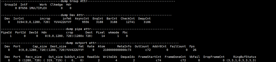
Debug Information
#cat /proc/mi_modules/mi_vif/mi_vif0
-
Debug Information Analysis
Record the current VIF usage status and Group/ Dev/ pipe/ outport attributes, you can get this information dynamically, which is convenient for debugging and testing.
-
Parameter Description
Parameter Description Group Attr GroupId Group ID Intf Protocol for entering data, please refer to MI_VIF_IntfMode_e Work Work mode, please refer to MI_VIF_WorkMode_e Clkedge Clock edge trigger mode, please refer to MI_VIF_ClkEdge_e Hdr Hdr type, please refer to MI_VIF_HDRType_e Dev Attr Dev Device id FsCnt Interrupt count of Frame start FdCnt Interrupt count of Frame done
incrop Input Corp Size, please refer to MI_VIF_DevAttr_t stInputRect infmt Input pixel format, please refer to MI_VIF_DevAttr_t eInputPixel capsel Field type, please refer to MI_VIF_DevAttr_t Field rstcnt Reset count, corresponding to (Fifo, Wdma, Fifo_Wdma) AsyncCnt/EnqCnt/ BarCnt/CheckCnt/ DequCnt MI internal Callback interface execution times DropCnt Drop frame count Pipe Attr PipeId Pipe id PortId Port id DevId Device id Hdn H2T1PMode enable, please refer to MI_VIF_DevAttr_t bEnH2T1PMode crop Mhal output crop size (Height will divide 2 in DI Mode) Dest Mhal output size (Height will divide 2 in DI Mode) Pixel Mhal output Pixel, transferred by MI pixel wkmode Pipe work mode, 0: Realtime,1: FrameMode Compress Please refer to MI_VIF_OutputPortAttr_t eCompressMode OutPort Attr Dev Device id Port Port id wFsNum Interrupt count of Wdma Frame start wLCNum Interrupt count of Wdma Line Count hit wDoneNum Interrupt count of Wdma Done DvCnt Double vsync count OsCnt Oversize count Cap_size Port Crop Size, please refer to MI_VIF_OutputPortAttr_t stCapRect Dest_size Output size, please refer to MI_VIF_OutputPortAttr_t stDestSize Fmt Output pixel format, please refer to MI_VIF_OutputPortAttr_t ePixFormat Rate Frame rate type, please refer to MI_VIF_OutputPortAttr_t eFrameRate CRC CRC on/off status
Atom The number of buffers held by driver MetaInfo Frame id OutCount Output frame count, only done frame, not include drop frame Addr0Cnt Frame address 0 count, means skip frame count FailCount Failed to get outputbuffer count EnqFailCount Count which failed to queue buffer to wdma Fps Frame per second Recv_size Vif hardware received size Out_size Port0 wdma size setting SubOut_size Port1 wdma size setting FifoDepth Buffer count in wdma fifo WdmaInactive Wdma is active or not, 0: active, 1: inactive
5.2. echo
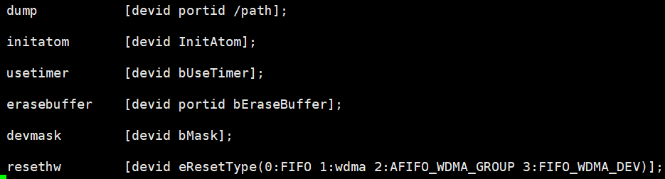
Echo help can view available commands:
# echo help >/proc/mi_modules/mi_vif/mi_vif0
| Function | Dump frame to the specified path. |
|---|---|
| Command | echo dump [devid portid path cnt dumpdrop] > /proc/mi_modules/mi_vif/mi_vif0 |
| Parameter Description |
devid: device id portid: port id path: Dumped path cnt: optional, frame count need to be dumped, default 1 dumpdrop: optional, only dump frame need to be dropped, default FALSE |
| Example | echo dump 0 0 /tmp > /proc/mi_modules/mi_vif/mi_vif0 echo dump 0 0 /tmp 2 1 > /proc/mi_modules/mi_vif/mi_vif0 |
| Function | Set the number of vif atoms. |
|---|---|
| Command | echo initatom [devid portid InitAtom] > /proc/mi_modules/mi_vif/mi_vif0 |
| Parameter Description |
devid: device id portid: port id InitAtom: The maximum number of buffers held by the Driver |
| Example | echo initatom 0 0 2 > /proc/mi_modules/mi_vif/mi_vif0 |
| Function | Set timer |
|---|---|
| Command | echo usetimer [devid bUseTimer] > /proc/mi_modules/mi_vif/mi_vif0 |
| Parameter Description |
devid: device id bUseTimer: Enable timer |
| Example | echo usetimer 0 1 > /proc/mi_modules/mi_vif/mi_vif0 |
| Function | Erase vif buffer |
|---|---|
| Command | echo erasebuffer [devid portid bEraseBuffer] > /proc/mi_modules/mi_vif/mi_vif0 |
| Parameter Description |
devid: device id portid: port id EraseBuffer: Enable to erase buffer |
| Example | echo erasebuffer 0 0 1 > /proc/mi_modules/mi_vif/mi_vif0 |
| Function | Set Dev Mask |
|---|---|
| Command | echo devmask [devid bMask] > /proc/mi_modules/mi_vif/mi_vif0 |
| Parameter Description |
devid: device id bmask: Enable mask |
| Example | echo devmask 0 1 > /proc/mi_modules/mi_vif/mi_vif0 |
| Function | Enable output port |
|---|---|
| Command | echo enport [devid portid bEn] > /proc/mi_modules/mi_vif/mi_vif0 |
| Parameter Description |
devid: device id portid: port id bEn: enable |
| Example | echo enport 0 0 1 > /proc/mi_modules/mi_vif/mi_vif0 |
| Function | Set output port attribute |
|---|---|
| Command | echo cfgport [devid portid crop(x,y,width,height) dest(width,height) pixel compress] > /proc/mi_modules/mi_vif/mi_vif0 |
| Parameter Description |
devid: device id portid: port id crop(x,y,width,height): output port crop position dest(width,height): output size Pixel: output port pixel format compress: compress mode |
| Example | echo cfgport 0 0 0 0 1280 720 1280 720 14 5 > /proc/mi_modules/mi_vif/mi_vif0 |
| Function | Reset vif |
|---|---|
| Command | echo resethw [devid eResetType] > /proc/mi_modules/mi_vif/mi_vif0 |
| Parameter Description |
devid: device id eResetType: reset position. 0:FIFO; 1:wdma; 2:AFIFO_WDMA_GROUP; 3:FIFO_WDMA_DEV |
| Example | echo resethw 0 3 > /proc/mi_modules/mi_vif/mi_vif0 |
| Function | Set fps threshold. When fps less than threshold, warning will be reported. |
|---|---|
| Command | echo fpsth [devid portid FpsTh FpsFloatTh] > /proc/mi_modules/mi_vif/mi_vif0 |
| Parameter Description |
devid: device id portid: port id FpsTh: fps integer threshold FpsFloatTh: fps decimal threshold |
| Example | echo enport 0 0 29 98 > /proc/mi_modules/mi_vif/mi_vif0 |
| Function | Set pts interval threshold. When pts is not in the range of threshold, warning will be reported. |
|---|---|
| Command | echo ptsth [devid portid ptsmin ptsmax] > /proc/mi_modules/mi_vif/mi_vif0 |
| Parameter Description |
devid: device id portid: port id ptsmin: pts interval min threshold(us) ptsmax: pts interval max threshold(us) |
| Example | echo ptsth 0 0 25000 40000 > /proc/mi_modules/mi_vif/mi_vif0 |
| Function | Trigger fifo full reset flow |
|---|---|
| Command | echo fifofull [devid bNeedReset] > /proc/mi_modules/mi_vif/mi_vif0 |
| Parameter Description |
devid: device id bNeedReset: set 1 to trigger fifo full reset flow |
| Example | echo fifofull 0 1 > /proc/mi_modules/mi_vif/mi_vif0 |
| Function | Enable CRC check |
|---|---|
| Command | echo crc [devid enable] > /proc/mi_modules/mi_vif/mi_vif0 |
| Parameter Description |
devid: device id enable: set 1 to enable CRC |
| Example | echo crc 0 1 > /proc/mi_modules/mi_vif/mi_vif0 |
| Function | Set MI VIF debug level |
|---|---|
| Command | echo debuglv [devid debuglevel] > /proc/mi_modules/mi_vif/mi_vif0 |
| Parameter Description |
devid: device id debuglevel: MI VIF debug level, default 0, off 0x0001 Mhal_Buff_Dbg 0x0002 CHECK_LOOP 0x0004 CHECK_ISR 0x0008 CHECK_FLOW 0x0080 CHECK_LATENCY |
| Example | echo debuglv 0 3 > /proc/mi_modules/mi_vif/mi_vif0 |
| Function | Enable VIF pattern gen |
|---|---|
| Command | echo patgen [group width height fps pixel multi bFieldEn Enable] > /proc/mi_modules/mi_vif/mi_vif0 |
| Parameter Description |
Group: group ID Width: pattern width Height: pattern height Fps: output frame per second Pixel: pattern pixel format Multi: can be set to 1chn/2chn/4chn, the same as BT656 multichn concept bFieldEn: enable DI mode Enable: enable pattern |
| Example | echo patgen 0 1280 720 25 14 4 0 1 > /proc/mi_modules/mi_vif/mi_vif0 |
| Function | Enable VIF data gen |
|---|---|
| Command | echo datagen [group Enable] > /proc/mi_modules/mi_vif/mi_vif0 |
| Parameter Description |
group: group ID Enable: enable data gen |
| Example | echo datagen 0 1 > /proc/mi_modules/mi_vif/mi_vif0 |
| Function | Force deque vif buffer, used for debugging when the buffer is stuck in vif. |
|---|---|
| Command | echo forcedeque [devid portid CurrentWriteAddr ValidCnt WdmaInactive] > /proc/mi_modules/mi_vif/mi_vif0 |
| Parameter Description |
devid: device id Portid: port id CurrentWriteAddr: address which WMDA is writing ValidCnt: buffer count which stay in WDMA FIFO WdmaInactive: wdma status, 0: active, 1: inactive |
| Example | echo forcedeque 0 0 0 0 1 > /proc/mi_modules/mi_vif/mi_vif0 |
| Function | Change VIF output buffer randomly |
|---|---|
| Command | echo changebuf [devid portid cnt bdump mode] > /proc/mi_modules/mi_vif/mi_vif0 |
| Parameter Description |
devid: device id portid: port id Cnt: buffer count which need to be changed bdump: optional, dump change buffer or not, default FALSE not dump Mode: optional, different mode to change buffer, default mode 0 0: Only change buffer by the count which user set 1: For SFBC0 compress, only change count which user set, but change position within SFBC0 PPS header 2: Change every output buffer, and not refer to parameter “cnt” 3: Change every output buffer, change position include 50% SFBC0 PPS and 50% Non-PPS, and not refer to parameter “cnt” |
| Example | echo changebuf 0 0 3 > /proc/mi_modules/mi_vif/mi_vif0 echo changebuf 0 0 3 1 2 > /proc/mi_modules/mi_vif/mi_vif0 |