MI IVE API
REVISION HISTORY
| Revision No. | Description |
Date |
|---|---|---|
| 2.03 | 04/12/2018 | |
| 2.04 | 06/05/2019 | |
| 2.05 | 10/09/2019 | |
| 2.06 | 09/16/2020 | |
| 2.07 | 10/14/2020 | |
| 2.08 | 08/13/2021 | |
| 2.09 | 08/26/2021 | |
| 2.10 | 01/26/2022 | |
| 2.11 | 03/15/2022 | |
| 2.12 | 03/18/2022 |
1. API REFERENCE
The MI IVE module provides the following APIs:
| Name of API | Function |
|---|---|
| MI_IVE_Create_Handle | Create IVE handle index and IVE handle |
| MI_IVE_Create | Create an IVE handle |
| MI_IVE_Destroy | Destroy an IVE handle |
| MI_IVE_Filter | Execute a 5x5 template filter task |
| MI_IVE_Csc | Execute a color space conversion task |
| MI_IVE_FilterAndCsc | Execute a composite task of template filter plus color space conversion |
| MI_IVE_Sobel | Execute a 5x5 template Sobel-like gradient calculation task |
| MI_IVE_MagAndAng | Execute a 5x5 template gradient magnitude and angle calculation task |
| MI_IVE_Dilate | Execute a Dilate task |
| MI_IVE_Erode | Execute an Erode task |
| MI_IVE_Thresh | Execute an image binarization task |
| MI_IVE_And | Execute an And task |
| MI_IVE_Sub | Execute a Subtract task |
| MI_IVE_Or | Execute an Or task |
| MI_IVE_Integ | Execute an integral graph statistics task |
| MI_IVE_Hist | Execute a histogram statistics task |
| MI_IVE_ThreshS16 | Execute an S16 data to 8-bit data thresholding task |
| MI_IVE_ThreshU16 | Execute a U16 data to U8 data thresholding task |
| MI_IVE_16BitTo8Bit | Execute a 16-bit data to 8-bit data linear transformation task |
| MI_IVE_OrdStatFilter | Execute a 3x3 template sequential statistic filtering task |
| MI_IVE_Map | Execute a Map (U8->U8 mapping assignment) task |
| MI_IVE_EqualizeHist | Execute a grayscale-image histogram equalization calculation task |
| MI_IVE_Add | Execute a weighted addition calculation task against two grayscale images |
| MI_IVE_Xor | Execute an XOR calculation task against two binary graphs |
| MI_IVE_Ncc | Execute a normalized cross-correlation calculation task against two images of the same resolution |
| MI_IVE_Ccl | Execute a connected region label task against binary images |
| MI_IVE_Gmm | Execute a GMM background modeling task |
| MI_IVE_CannyHysEdge | Execute a Canny strong edge extraction task against grayscale images |
| MI_IVE_CannyEdge | Execute the second half of Canny strong edge extraction task: connecting edge points to form a Canny edge map |
| MI_IVE_Lbp | Execute an LBP calculation task |
| MI_IVE_NormGrad | Execute a normalized gradient calculation task, in which the gradient average components are normalized to S8 |
| MI_IVE_LkOpticalFlow | Execute a single layer LK optical flow calculation task |
| MI_IVE_Sad | Calculate 16-bit/8-bit SAD images of 4x4/8x8/16x16 blocks for two images, and threshold output for SAD |
| MI_IVE_Bernsen | Execute a Bernsen thresh task for the 3x3 and 5x5 windows. |
| MI_IVE_LineFilterHor | Execute a horizontal density filter task for binary images. |
| MI_IVE_LineFilterVer | Execute a vertical density filter task for binary images. |
| MI_IVE_NoiseRemoveHor | Execute a horizontal noise removal task for binary images. |
| MI_IVE_NoiseRemoveVer | Execute a vertical noise removal task for binary images. |
| MI_IVE_AdpThresh | Execute an adaptive thresh task. |
| MI_IVE_Resize | Execute an image scaling task. |
| MI_IVE_BAT | Execute the horizontal or vertical alternating time for binary images. |
| MI_IVE_Acc | Execute an accumulation task for two gray-scale images. |
| MI_IVE_Matrix_Transform | Execute the operation of matrix multiplication. |
| MI_IVE_Image_Dot | Execute the operation of dot product. |
| MI_IVE_Shift_Detector | Execute the operation of object tracking. |
| MI_IVE_AlphaBlending | Execute an independent weighted addition calculation task against two grayscale images. |
1.1. MI_IVE_Create_Handle
-
Function
Create IVE handle index and IVE handle.
-
Syntax
MI_IVE_HANDLE MI_IVE_Create_Handle();
-
Return Value
Return Value Description Handle index range: [0, MI_IVE_HANDLE_MAX] MI_IVE_HANDLE_MAX Failed. -
Requirement
-
Header: mi_comm_ive.h, mi_ive.h, mi_ive.h
-
Library: libmi_ive.a
-
-
Note
- This function already included MI_IVE_Create, it is redundant for calling IVE_Create again.
1.2. MI_IVE_Create
-
Function
Create an IVE handle
-
Syntax
MI_IVE_HANDLE MI_IVE_Create(MI_IVE_HANDLE hHandle);
-
Parameter
Parameter Name Description Input/Output hHandle Regional handle number.
Must be an unused hHandle number.
Parameter range: [0, MI_IVE_HANDLE_MAX)Input -
Return Value
Return Value Description 0 Successful. Non-zero Failed. Please refer to ERROR CODE. -
Requirement
-
Header: mi_comm_ive.h, mi_ive.h, mi_ive.h
-
Library: libmi_ive.a
-
1.3. MI_IVE_Destroy
-
Function
Release an IVE handle
-
Syntax
MI_IVE_HANDLE MI_IVE_Destroy(MI_IVE_HANDLE hHandle);
-
Parameter
Parameter Name Description Input/Output hHandle Regional handle number.
Parameter range: [0, MI_IVE_HANDLE_MAX).Input -
Return Value
Return Value Description 0 Successful. Non-zero Failed. Please refer to ERROR CODE. -
Requirement
-
Header: mi_comm_ive.h, mi_ive.h, mi_ive.h
-
Library: libmi_ive.a
-
1.4. MI_IVE_Filter
-
Function
Execute a 5x5 template filter task. By configuring different template coefficients, you can realize different filters.
-
Syntax
MI_S32 MI_IVE_Filter(MI_IVE_HANDLE hHandle,
MI_IVE_SrcImage_t *pstSrc,
MI_IVE_DstImage_t *pstDst,
MI_IVE_FilterCtrl_t *pstFltCtrl, MI_BOOL bInstant);
-
Parameter
Parameter Name Description Input/Output hHandle Regional handle number. Parameter range: [0, MI_IVE_HANDLE_MAX). Input pstSrc Source image pointer. Cannot be null. Input pstDst Output image pointer. Cannot be null. Width and height same as pstSrc. Output pstFltCtrl Control info pointer. Cannot be null. Input bInstant Reserved. Input Parameter Name Supported Image Type Address Alignment Resolution pstSrc U8C1, YUV420SP, YUV422SP 16 byte 64x64 ~ 1920x1024 pstDst Same as pstSrc 16 byte Same as pstSrc NOTE: U8C1, YUV420SP, and YUV422SP are the short form of MI_IVE_ImageType_e member. Other members will adopt the same naming rule throughout the rest of the document.
-
Return Value
Return Value Description 0 Successful. Non-zero Failed. Please refer to ERROR CODE. -
Requirement
-
Header: mi_comm_ive.h, mi_ive.h, mi_ive.h
-
Library: libmi_ive.a
-
-
Note
-
When the source data type is YUV420SP or YUV422SP, the output data stride must be consistent.
-
For the filter calculation formula, please refer to the figure below.
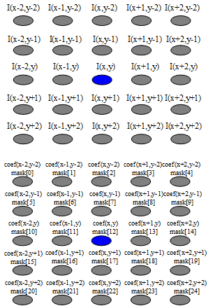 I_{out}(x,y)={\sum_{-2\leqslant i\leqslant2} \sum_{-2\leqslant j\leqslant2} I_{in}(x+i,y+j)*coef(x+i,y+j)}>>norm
Fig 1-1 Filter Calculation Formula
Where, I(x,y) refers to pstSrc, Iout(x,y) refers to pstDst, coef (mask) refers to as8Mask[MI_IVE_MASK_SIZE_5X5] in pstFltCtrl, and norm refers to u8Norm in pstFltCtrl.
-
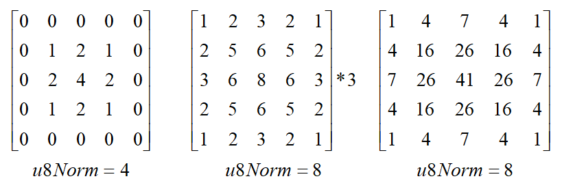
The classic Gaussian template is as illustrated below:
MI_IVE_Data_t two-dimensional data stride refers to the number of bytes in one line of two-dimensional data, i.e., the case shown in Figure 2 where n=8.
MI_IVE_Data_t can be looked upon as an image with “pixels” presented in 8-bit addressing. In this light, the stride can be interpreted as the number of units in one line as calculated on the basis of "pixels" of an image or two-dimensional data.

Fig 1-2: Data Stride
-
Alignment
For quick access to the start address of memory or data across rows, HW requires that the memory address or memory stride be a multiple of the alignment factor.
-
Data memory start address alignment
The current IVE operator requires that the Input/Output be 1-, 2-, or 16-byte aligned. For detailed parameter requirement, please refer to the respective APIs.
-
Stride alignment
For generalized two-dimensional images, the stride of two-dimensional single-component data and one-dimensional array data must satisfy the 16 "pixel" alignment rule.
-
-
Input/Output data type (for detailed structure definition, please refer to Chapter 2.IVE DATA TYPE)
-
Generalized two-dimensional image data
For MI_IVE_Image_t, MI_IVE_SrcImage_t, and MI_IVE_DstImage_t, please refer to MI_IVE_ImageType_e for the image type.
Note: Currently the width and height of the generalized two-dimensional image data for the operator input/output are even number.
-
-
Two-dimensional single-component data
MI_IVE_Data_t, two-dimensional data in byte unit, is mainly used for DMA, etc. Depending on the image type, MI_IVE_Image_t can be converted into single or multiple MI_IVE_Data_t.
-
One-dimensional data
MI_IVE_MemInfo_t, MI_IVE_SrcMemInfo_t, and MI_IVE_DstMemInfo_t are one-dimensional data such as histogram statistical data, GMM model data, and LK optical flow corner input, etc.
-
Generalized two-dimensional image type
Type Image Description Memory Address Stride E_MI_IVE_IMAGE_TYPE_U8C1 8-bit unsigned single channel image Only u32PhyAddr[0] and pu8VirAddr[0] in [MI_IVE_Image_t are used Only u16Stride[0] is used
-
-
Related API
MI_IVE_FilterAndCsc
MI_IVE_OrdStatFilter
1.5. MI_IVE_Csc
-
Function
Execute a color space conversion task for color space conversion with respect to YUV2RGB\YUV2BGR\RGB2YUV\BGR2YUV.
-
Syntax
MI_S32 MI_IVE_Csc(MI_IVE_HANDLE hHandle,
MI_IVE_SrcImage_t *pstSrc, MI_IVE_DstImage_t *pstDst, MI_IVE_CscCtrl_t
*pstCscCtrl, MI_BOOL bInstant);
-
Parameter
Parameter Name Description Input/Output hHandle Regional handle number. Parameter range: [0, MI_IVE_HANDLE_MAX). Input pstSrc Source image pointer. Cannot be null. Input pstDst Output image pointer. Cannot be null. Width and height same as pstSrc. Output pstCscCtrl Control info pointer. Cannot be null. Input bInstant Reserved. Input Parameter Name Supported Image Type Address Alignment Resolution pstSrc YUV420SP(NV12)、YUV422SP、U8C3_PLANAR、U8C3_PACKAGE、YUV420SP_NV21 16 byte 64x64 ~ 1920x1080 pstDst YUV420SP(NV12)、YUV422SP、U8C3_PLANAR、U8C3_PACKAGE、YUV420SP_NV21 16 byte Same as pstSrc -
Return Value
Return Value Description 0 Successful. Non-zero Failed. Please refer to ERROR CODE. -
Requirement
-
Header: mi_comm_ive.h, mi_ive.h, mi_ive.h
-
Library: libmi_ive.a
-
-
Note
-
When the output data type is U8C3_PLANAR, YUV420SP or YUV422SP, the output data stride must be consistent.
-
Different work modes have different output parameter ranges. For details, please refer to MI_IVE_CscMode_e.
-
Conversion formula as below :
\begin{bmatrix} &Y \\ &U \\ &V \\ \end{bmatrix} = \begin{bmatrix} &0.299 &0.587 &0.114 \\ &-0.169 &-0.331 &0.5 \\ &0.5 &-0.419 &-0.081 \\ \end{bmatrix} \begin{bmatrix} &R \\ &G \\ &B \\ \end{bmatrix} + \begin{bmatrix} &0 \\ &128 \\ &128 \\ \end{bmatrix}\begin{bmatrix} &R \\ &G \\ &B \\ \end{bmatrix} = \begin{bmatrix} &1 &-0.00093 &1.401687 \\ &1 &-0.3437 &-0.71417 \\ &1 &1.77216 &0.00099 \\ \end{bmatrix} \begin{bmatrix} &Y \\ &U-128 \\ &V-128 \\ \end{bmatrix}
-
-
Related API
1.6. MI_IVE_FilterAndCsc
-
Function
Execute a composite task of 5x5 template filter plus YUV2RGB color space conversion, to accomplish two functions by one single execution.
-
Syntax
MI_S32 MI_IVE_FilterAndCsc(MI_IVE_HANDLE hHandle,
MI_IVE_SrcImage_t
*pstSrc,
MI_IVE_DstImage_t
*pstDst,
MI_IVE_FilterAndCscCtrl_t
*pstFltCscCtrl, MI_BOOL bInstant);
-
Parameter
Parameter Name Description Input/Output hHandle Regional handle number. Parameter range: [0, MI_IVE_HANDLE_MAX). Input pstSrc Source image pointer. Cannot be null. Input pstDst Input image pointer. Cannot be null. Width and height same as pstSrc. Output pstFltCscCtrl Control info pointer. Cannot be null. Input bInstant Reserved. Input Parameter Name Supported Image Type Address Alignment Resolution pstSrc YUV420SP, YUV422SP 16 byte 64x64 ~ 1920x1024 pstDst U8C3_PLANAR, U8C3_PACKAGE 16 byte Same as pstSrc -
Return Value
Return Value Description 0 Successful. Non-zero Failed. Please refer to ERROR CODE. -
Requirement
-
Header: mi_comm_ive.h, mi_ive.h, mi_ive.h
-
Library: libmi_ive.a
-
-
Note
-
When the output data type is U8C3_PLANAR, the output data stride must be consistent.
-
Only the four work modes of YUV2RGB are supported. For details, please refer to MI_IVE_CscMode_e.
-
-
Related API
1.7. MI_IVE_Sobel
-
Function
Execute a 5x5 template Sobel-like gradient calculation task
-
Syntax
MI_S32 MI_IVE_Sobel(MI_IVE_HANDLE hHandle, MI_IVE_SrcImage_t *pstSrc,
MI_IVE_DstImage_t *pstDstH, MI_IVE_DstImage_t *pstDstV, MI_IVE_SobelCtrl_t
*pstSobelCtrl, MI_BOOL bInstant);
-
Parameter
Parameter Name Description Input/Output hHandle Regional handle number. Parameter range: [0, MI_IVE_HANDLE_MAX). Input pstSrc Source image pointer. Cannot be null. Input pstDstH Gradient component image H pointer gained by template filtering. According to pstSobelCtrl→eOutCtrl, this parameter cannot be null if output is required. Width and height same as pstSrc. Output pstDstV Gradient component image V pointer gained by transposed template filtering. According to pstSobelCtrl→eOutCtrl, this parameter cannot be null if output is required. Width and height same as pstSrc. Output pstSobelCtrl Control info pointer. Cannot be null. Input bInstant Reserved. Input Parameter Name Supported Image Type Address Alignment Resolution pstSrc U8C1 16 byte 64x64 ~ 1920x1024 pstDstH S16C1 16 byte Same as pstSrc pstDstV S16C1 16 byte Same as pstSrc -
Return Value
Return Value Description 0 Successful. Non-zero Failed. Please refer to ERROR CODE. -
Requirement
-
Header: mi_comm_ive.h, mi_ive.h, mi_ive.h
-
Library: libmi_ive.a
-
-
Note
-
Three output modes are available for configuration. Please refer to MI_IVE_SobelOutCtrl_e.
-
When the output mode is E_MI_IVE_SOBEL_OUT_CTRL_BOTH, the stride of pstDstH and the stride of pstDstV must be consistent.
-
Sobel calculation formula is as shown in the figure below.
H_{out}(x,y)=\sum_{-2\leqslant i\leqslant2}\sum_{-2\leqslant j\leqslant2}I(x+i,y+j)*coef(x+i,y+j)V_{out}(x,y)=\sum_{-2\leqslant i\leqslant2}\sum_{-2\leqslant j\leqslant2}I(x+i,y+j)*coef(x+i,y+j)Fig 1-3 Sobel Calculation Formula
Where, I (x, y) refers to pstSrc, Hout(x, y) refers to pstDstH, Vout(x, y) refers to pstDstV, and coef (mask) refers to as8Mask[MI_IVE_MASK_SIZE_5X5] in pstSobelCtrl.
-
Sobel template
\begin{bmatrix} &0 &0 &0 &0 &0 \\ &0 &-1 &0 &1 &0 \\ &0 &-2 &0 &2 &0 \\ &0 &-1 &0 &1 &0 \\ &0 &0 &0 &0 &0 \end{bmatrix} \begin{bmatrix} &0 &0 &0 &0 &0 \\ &0 &-1 &-2 &-1 &0 \\ &0 &0 &0 &0 &0 \\ &0 &1 &2 &1 &0 \\ &0 &0 &0 &0 &0 \end{bmatrix}\begin{bmatrix} &-1 &-2 &0 &2 &1 \\ &-4 &-8 &0 &8 &4 \\ &-6 &-12 &0 &12 &6 \\ &-4 &-8 &0 &8 &4 \\ &-1 &-2 &0 &2 &1 \end{bmatrix} \begin{bmatrix} &-1 &-4 &-6 &-4 &-1 \\ &-2 &-8 &-12 &-8 &-2 \\ &0 &0 &0 &0 &0 \\ &2 &8 &12 &8 &2 \\ &1 &4 &6 &4 &1 \end{bmatrix} -
Scharr template
\begin{bmatrix} &0 &0 &0 &0 &0 \\ &0 &-3 &0 &3 &0 \\ &0 &-10 &0 &10 &0 \\ &0 &-3 &0 &3 &0 \\ &0 &0 &0 &0 &0 \end{bmatrix} \begin{bmatrix} &0 &0 &0 &0 &0 \\ &0 &-3 &-10 &-3 &0 \\ &0 &0 &0 &0 &0 \\ &0 &3 &10 &3 &0 \\ &0 &0 &0 &0 &0 \end{bmatrix} -
Laplace template
\begin{bmatrix} &0 &0 &0 &0 &0 \\ &0 &0 &1 &0 &0 \\ &0 &1 &-4 &1 &0 \\ &0 &0 &1 &0 &0 \\ &0 &0 &0 &0 &0 \end{bmatrix} \begin{bmatrix} &0 &0 &0 &0 &0 \\ &0 &0 &-1 &0 &0 \\ &0 &-1 &4 &-1 &0 \\ &0 &0 &-1 &0 &0 \\ &0 &0 &0 &0 &0 \end{bmatrix}\begin{bmatrix} &0 &0 &0 &0 &0 \\ &0 &1 &1 &1 &0 \\ &0 &1 &-8 &1 &0 \\ &0 &1 &1 &1 &0 \\ &0 &0 &0 &0 &0 \end{bmatrix} \begin{bmatrix} &0 &0 &0 &0 &0 \\ &0 &-1 &-1 &-1 &0 \\ &0 &-1 &8 &-1 &0 \\ &0 &-1 &-1 &-1 &0 \\ &0 &0 &0 &0 &0 \end{bmatrix}
-
-
Related API
1.8. MI_IVE_MagAndAng
-
Function
Execute a 5x5 template gradient magnitude and angle calculation task.
-
Syntax
MI_S32 MI_IVE_MagAndAng(MI_IVE_HANDLE hHandle,
MI_IVE_SrcImage_t *pstSrc,
MI_IVE_DstImage_t *pstDstMag,
MI_IVE_DstImage_t *pstDstAng,
MI_IVE_MagAndAngCtrl_t *pstMagAndAngCtrl, MI_BOOL bInstant);
-
Parameter
Parameter Name Description Input/Output hHandle Regional handle number. Parameter range: [0, MI_IVE_HANDLE_MAX). Input pstSrc Source image pointer. Cannot be null. Input pstDstMag Output magnitude image pointer. Cannot be null. Width and height same as pstSrc. Output pstDstAng Output angle image pointer. According to pstMagAndAngCtrl→eOutCtrl, this parameter cannot be null if output is required. Width and height same as pstSrc. Output pstMagAndAngCtrl Control info pointer. Cannot be null. Input bInstant Reserved. Input Parameter Name Supported Image Type Address Alignment Resolution pstSrc U8C1 16 byte 64x64 ~ 1920x1024 pstDstMag U16C1 16 byte Same as pstSrc pstDstAng U8C1 16 byte Same as pstSrc -
Return Value
Return Value Description 0 Successful. Non-zero Failed. Please refer to ERROR CODE. -
Requirement
-
Header: mi_comm_ive.h, mi_ive.h, mi_ive.h
-
Library: libmi_ive.a
-
-
Note
-
Two output modes can be configured. For details, please refer to MI_IVE_MagAndAngOutCtrl_e.
-
When the output mode is E_MI_IVE_MAG_AND_ANG_OUT_CTRL_MAG_AND_ANG, the stride of pstDstMag and the stride of pstDstAng must be consistent.
-
User can utilize pstMagAndAngCtrl→u16Thr to do thresholding operation against magnitude map (to achieve EOH), the calculation formula is as follows:
Mag(x,y)=\left\{ \begin{aligned} 0 , Mag(x,y) < u16Thr \\ Mag(x,y) ,Mag(x,y)\geq u16Thr \end{aligned} \right.Where, Mag(x, y) refers to pstDstMag.
Fig 1-4: MagAndAng Calculation Formula
H_{out}(x,y)=\sum_{-2\leqslant i\leqslant2}\sum_{-2\leqslant j\leqslant2}I(x+i,y+j)*coef(x+i,y+j)V_{out}(x,y)=\sum_{-2\leqslant i\leqslant2}\sum_{-2\leqslant j\leqslant2}I(x+i,y+j)*coef(x+i,y+j)Mag(x,y)=abs(H_{out}(x,y))+abs(V_{out}(x,y))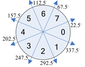
θ(x, y) takes the direction value corresponding to 0 to 7 in the above figure according to Hout(x, y), Vout(x, y) and arctan(Vout/Hout).
Where, I(x,y) refers to pstSrc, Mag(x,y) refers to pstDstMag, θ(x,y) refers to pstDstAng, and coef(mask) refers to as8Mask[MI_IVE_MASK_SIZE_5X5] in pstMagAndAngCtrl.
-
-
Related API
1.9. MI_IVE_Dilate
-
Function
Execute a binary image 5x5 template dilating task.
-
Syntax
MI_S32 MI_IVE_Dilate(MI_IVE_HANDLE hHandle,
MI_IVE_SrcImage_t *pstSrc,
MI_IVE_DstImage_t *pstDst,
MI_IVE_DilateCtrl_t *pstDilateCtrl, MI_BOOL bInstant);
-
Parameter
Parameter Name Description Input/Output hHandle Regional handle number. Parameter range: [0, MI_IVE_HANDLE_MAX). Input pstSrc Source image pointer. Cannot be null. Input pstDst Output image pointer. Cannot be null. Width and height same as pstSrc. Output pstDilateCtrl Control info pointer. Input bInstant Reserved. Input Parameter Name Supported Image Type Address Alignment Resolution pstSrc U8C1 binary image 16 byte 64x64 ~ 1920x1024 pstDst U8C1 binary image 16 byte Same as pstSrc -
Return Value
Return Value Description 0 Successful. Non-zero Failed. Please refer to ERROR CODE. -
Requirement
-
Header: mi_comm_ive.h, mi_ive.h, mi_ive.h
-
Library: libmi_ive.a
-
-
Note
The template coefficient can only be 0 or 255.
\begin{bmatrix} &0 &0 &0 &0 &0 \\ &0 &0 &255 &0 &0 \\ &0 &255 &255 &255 &0 \\ &0 &0 &255 &0 &0 \\ &0 &0 &0 &0 &0 \end{bmatrix} \begin{bmatrix} &0 &0 &0 &0 &0 \\ &0 &255 &255 &255 &0 \\ &0 &255 &255 &255 &0 \\ &0 &255 &255 &255 &0 \\ &0 &0 &0 &0 &0 \end{bmatrix}\begin{bmatrix} &0 &255 &255 &255 &0 \\ &255 &255 &255 &255 &255 \\ &255 &255 &255 &255 &255 \\ &255 &255 &255 &255 &255 \\ &0 &255 &255 &255 &0 \end{bmatrix} \begin{bmatrix} &255 &255 &255 &255 &255 \\ &255 &255 &255 &255 &255 \\ &255 &255 &255 &255 &255 \\ &255 &255 &255 &255 &255 \\ &255 &255 &255 &255 &255 \end{bmatrix}Fig 1-5: Dilate Calculation Formula
I_{out}(x,y)=O_{-2\leqslant i\leqslant2}(O_{-2\leqslant j\leqslant2}(f(i,j)))Where,
f(i,j)=I(x-i,y-j)\&coef(x-i,y-j)O_{-2\leqslant i\leqslant 2}=g(-2)|g(-1)|g(0)|g(1)|g(2)In the formula | is a bit or operation, & is a bit and operation, and % is a remainder operation. I(x,y) refers to pstSrc, Iout (x,y) refers to pstDst, and coef(mask) refers to au8Mask[MI_IVE_MASK_SIZE_5X5] in pstDilateCtrl.
-
Related API
1.10. MI_IVE_Erode
-
Function
Execute a binary image 5x5 template erosion task.
-
Syntax
MI_S32 MI_IVE_Erode(MI_IVE_HANDLE hHandle,
MI_IVE_SrcImage_t *pstSrc,
MI_IVE_DstImage_t *pstDst,
MI_IVE_ErodeCtrl_t *pstErodeCtrl,MI_BOOL bInstant);
-
Parameter
Parameter Name Description Input/Output hHandle Regional handle number. Parameter range: [0, MI_IVE_HANDLE_MAX). Input pstSrc Source image pointer. Cannot be null. Input pstDst Output image pointer. Cannot be null. Width and height same as pstSrc. Output pstErodeCtrl Control info pointer. Cannot be null. Input bInstant Reserved. Input Parameter Name Supported Image Type Address Alignment Resolution pstSrc U8C1 binary image 16 byte 64x64 ~ 1920x1024 pstDst U8C1 binary image 16 byte Same as pstSrc -
Return Value
Return Value Description 0 Successful. Non-zero Failed. Please refer to ERROR CODE. -
Requirement
-
Header: mi_comm_ive.h, mi_ive.h, mi_ive.h
-
Library: libmi_ive.a
-
-
Note
The template coefficient can only be 0 or 255.
\begin{bmatrix} &0 &0 &0 &0 &0 \\ &0 &0 &255 &0 &0 \\ &0 &255 &255 &255 &0 \\ &0 &0 &255 &0 &0 \\ &0 &0 &0 &0 &0 \end{bmatrix} \begin{bmatrix} &0 &0 &0 &0 &0 \\ &0 &255 &255 &255 &0 \\ &0 &255 &255 &255 &0 \\ &0 &255 &255 &255 &0 \\ &0 &0 &0 &0 &0 \end{bmatrix}\begin{bmatrix} &0 &255 &255 &255 &0 \\ &255 &255 &255 &255 &255 \\ &255 &255 &255 &255 &255 \\ &255 &255 &255 &255 &255 \\ &0 &255 &255 &255 &0 \end{bmatrix} \begin{bmatrix} &255 &255 &255 &255 &255 \\ &255 &255 &255 &255 &255 \\ &255 &255 &255 &255 &255 \\ &255 &255 &255 &255 &255 \\ &255 &255 &255 &255 &255 \end{bmatrix}Fig 1-6: Erode Calculation Formula
I_{out}(x,y)=O_{-2\leqslant i\leqslant2}(O_{-2\leqslant i\leqslant2}(f(i,j)))Where,
f(i,j)=I(x-i,y-j)|(255-coef(x-i,y-j))O_{-2\leqslant i\leqslant2}(g(k))=g(-2)\&g(-1)\&g(0)\&g(1)\&g(2)In the formula | is a bit or operation, & is a bit and operation, and % is a remainder operation. I (x, y) refers to pstSrc, Iout (x, y) refers to pstDst, and coef (mask) refers to au8Mask[MI_IVE_MASK_SIZE_5X5] in pstErodeCtrl.
-
Related API
1.11. MI_IVE_Thresh
-
Function
Execute a grayscale image thresholding task.
-
Syntax
MI_S32 MI_IVE_Thresh(MI_IVE_HANDLE hHandle,
MI_IVE_SrcImage_t *pstSrc,
MI_IVE_DstImage_t *pstDst,
MI_IVE_ThreshCtrl_t *pstThrCtrl, MI_BOOL bInstant);
-
Parameter
Parameter Name Description Input/Output hHandle Regional handle number. Parameter range: [0, MI_IVE_HANDLE_MAX). Input pstSrc Source image pointer. Cannot be null. Input pstDst Output image pointer. Cannot be null. Width and height same as pstSrc. Output pstThrCtrl Control info pointer. Input bInstant Reserved. Input Parameter Name Supported Image Type Address Alignment Resolution pstSrc U8C1 1 byte 64x64 ~ 1920x1080 pstDst U8C1 1 byte Same as pstSrc -
Return Value
Return Value Description 0 Successful. Non-zero Failed. Please refer to ERROR CODE. -
Requirement
-
Header: mi_comm_ive.h, mi_ive.h, mi_ive.h
-
Library: libmi_ive.a
-
-
Note
-
Eight operation modes are available for configuration. For details, please refer to MI_IVE_ThreshMode_e.
-
The calculation formula is as follows:
E_MI_IVE_THRESH_MODE_BINARY:
I_{out}(x,y)=\left\{ \begin{aligned} minVal I(x,y)\leqslant lowThr \\ maxVal I(x,y)> lowThr \end{aligned} \right.midVal, highThr do not require to be assigned.
E_MI_IVE_THRESH_MODE_TRUNC:
I_{out}(x,y)=\left\{ \begin{aligned} I(x,y),I(x,y)\leqslant lowThr \\ maxVal,I(x,y)>lowThr \end{aligned} \right.minVal, midVal, highThr do not require to be assigned.
E_MI_IVE_THRESH_MODE_TO_MINVAL:
I_{out}(x,y)=\left\{ \begin{aligned} minVal,I(x,y)\leqslant lowThr \\ I(x,y),I(x,y)> lowThr \end{aligned} \right.midVal, maxVal, highThr do not require to be assigned.
E_MI_IVE_THRESH_MODE_MIN_MID_MAX:
I_{out}(x,y)=\left\{ \begin{aligned} minVal,I(x,y)\leqslant lowThr \\ midVal,lowThr\leqslant I(x,y)\leqslant highThr \\ maxVal,I(x,y)>highThr \end{aligned} \right.E_MI_IVE_THRESH_MODE_ORI_MID_MAX:
I_{out}(x,y)=\left\{ \begin{aligned} I(x,y),I(x,y)\leqslant lowThr \\ midVal,lowThr\leqslant I(x,y)\leqslant highThr \\ maxVal,I(x,y)>highThr \end{aligned} \right.minVal does not require to be assigned.
E_MI_IVE_THRESH_MODE_MIN_MID_ORI:
I_{out}(x,y)=\left\{ \begin{aligned} minVal,I(x,y) \leqslant lowThr \\ midVal,lowThr\leqslant I(x,y)\leqslant highThr \\ I(x,y),I(x,y)>highThr \end{aligned} \right.maxVal does not require to be assigned.
E_MI_IVE_THRESH_MODE_MIN_ORI_MAX:
I_{out}(x,y)=\left\{ \begin{aligned} minVal,I(x,y) \leqslant lowThr \\ I(x,y),lowThr\leqslant I(x,y)\leqslant highThr \\ maxVal,I(x,y)>highThr \end{aligned} \right.midVal does not require to be assigned.
E_MI_IVE_THRESH_MODE_ORI_MID_ORI:
I_{out}(x,y)=\left\{ \begin{aligned} I(x,y),I(x,y) \leqslant lowThr \\ midVal,lowThr\leqslant I(x,y)\leqslant highThr \\ I(x,y),I(x,y)>highThr \end{aligned} \right.minVal, maxVal do not require to be assigned
Where, I(x,y) refers to pstSrc, Iout(x,y) refers to pstDst, and mode, lowThr, highThr, minVal, midVal and maxVal refer respectively to eMode, u8LowThr, u8HighThr, u8MinVal, u8MidVal and u8MaxVal in pstThrCtrl. Please refer to Figure 7 for the detailed illustration.
-
u8MinVal, u8MidVal and u8MaxVal in pstThrCtrl do not need to satisfy the size relationship signified by the variable name.
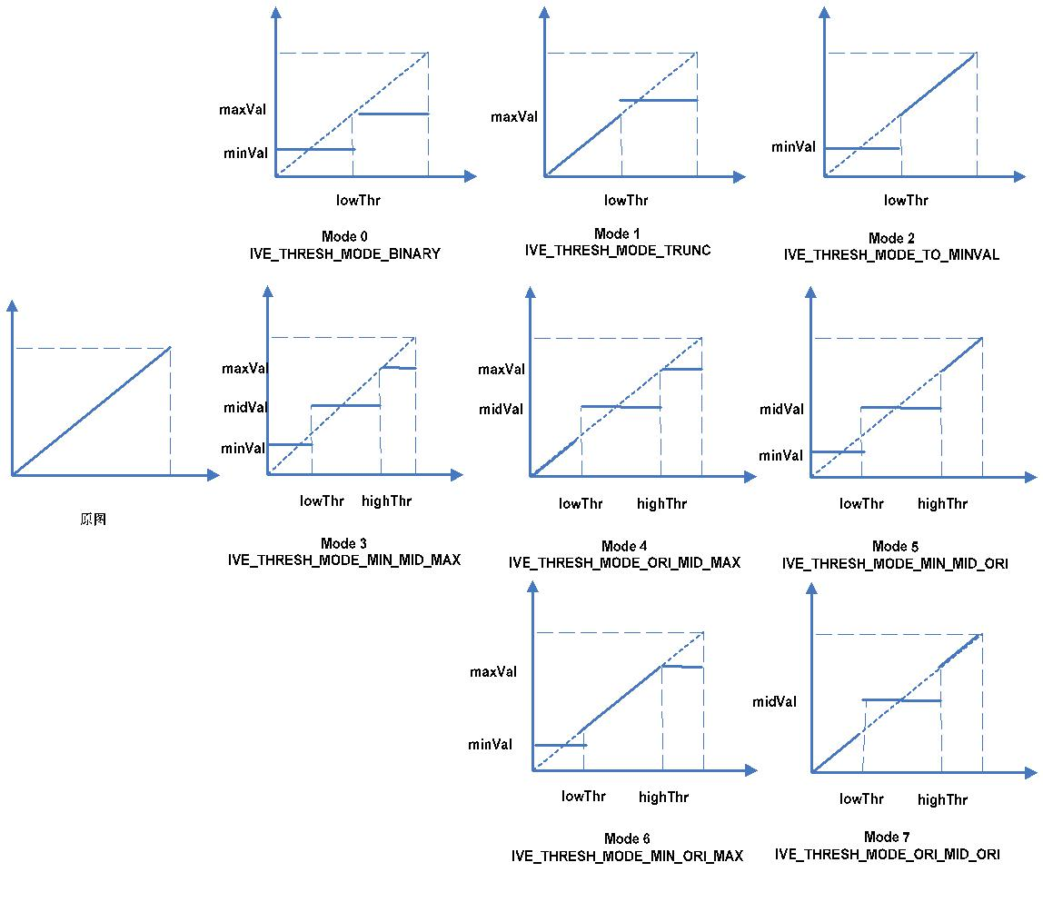
Fig 1-7: 8 Thresholding Modes
-
-
Related API
1.12. MI_IVE_And
-
Function
Execute an AND task against two binary images.
-
Syntax
MI_S32 MI_IVE_And(MI_IVE_HANDLE hHandle,
MI_IVE_SrcImage_t *pstSrc1,
MI_IVE_SrcImage_t *pstSrc2,
MI_IVE_DstImage_t *pstDst, MI_BOOL bInstant);
-
Parameter
Parameter Name Description Input/Output hHandle Regional handle number. Parameter range: [0, MI_IVE_HANDLE_MAX). Input pstSrc1 Source image 1 pointer. Cannot be null. Input pstSrc2 Source image 2 pointer. Cannot be null. Width and height same as pstSrc1. Input pstDst Output image pointer. Cannot be null. Width and height same as pstSrc1. Output bInstant Reserved. Input Parameter Name Supported Image Type Address Alignment Resolution pstSrc1 U8C1 binary image 1 byte 64x64 ~ 1920x1080 pstSrc2 U8C1 binary image 1 byte Same as pstSrc1 pstDst U8C1 binary image 1 byte Same as pstSrc1 -
Return Value
Return Value Description 0 Successful. Non-zero Failed. Please refer to ERROR CODE. -
Requirement
-
Header: mi_comm_ive.h, mi_ive.h, mi_ive.h
-
Library: libmi_ive.a
-
-
Note
The calculation formula is as follows:
I_{out}(x,y)=I_{src1}(x,y)\&I_{src2}(x,y)Where, (, ) 1 I x y src refers to pstSrc1, (, ) 2 I x y src refers to pstSrc2, and I (x, y) out refers to pstDst
-
Related API
1.13. MI_IVE_Sub
-
Function
Execute a SUBTRACT task against two grayscale images.
-
Syntax
MI_S32 MI_IVE_Sub(MI_IVE_HANDLE hHandle,
MI_IVE_SrcImage_t *pstSrc1,
MI_IVE_SrcImage_t *pstSrc2,
MI_IVE_DstImage_t *pstDst,
MI_IVE_SubCtrl_t *pstSubCtrl, MI_BOOL bInstant);
-
Parameter
Parameter Name Description Input/Output hHandle Regional handle number. Parameter range: [0, MI_IVE_HANDLE_MAX). Input pstSrc1 Source image 1 pointer. Cannot be null. Input pstSrc2 Source image 2 pointer. Cannot be null. Width and height same as pstSrc1. Input pstDst Output image pointer. Cannot be null. Width and height same as pstSrc1. Output pstSubCtrl Control info pointer. Cannot be null. Input bInstant Reserved. Input Parameter Name Supported Image Type Address Alignment Resolution pstSrc1 U8C1 1 byte 64x64 ~ 1920x1080 pstSrc2 U8C1 1 byte Same as pstSrc1 pstDst U8C1, S8C1 1 byte Same as pstSrc1 -
Return Value
Return Value Description 0 Successful. Non-zero Failed. Please refer to ERROR CODE. -
Requirement
-
Header: mi_comm_ive.h, mi_ive.h, mi_ive.h
-
Library: libmi_ive.a
-
-
Note
-
Two output formats are available for configuration. For details, please refer to MI_IVE_SubMode_e.
-
E_MI_IVE_SUB_MODE_ABS
calculation formula: Iout(x,y)=abs(I*src*1(x,y)Isrc*2(*x,y))
Output format: U8C1 -
E_MI_IVE_SUB_MODE_SHIFT
calculation formula: Iout(x,y)=(I*src*1(x,y)Isrc*2(*x,y))>>1
Output format: S8C1
where, Isrc*1(*x,y) refers to pstSrc1, Isrc*2(*x,y) refers to pstSrc2, and Iout(x,y) refers to pstDst.
-
-
Related API
1.14. MI_IVE_Or
-
Function
Execute an OR task against two binary images.
-
Syntax
MI_S32 MI_IVE_Or(MI_IVE_HANDLE hHandle,
MI_IVE_SrcImage_t *pstSrc1,
MI_IVE_SrcImage_t *pstSrc2,
MI_IVE_DstImage_t *pstDst, MI_BOOL bInstant);
-
Parameter
Parameter Name Description Input/Output hHandle Regional handle number. Parameter range: [0, MI_IVE_HANDLE_MAX). Input pstSrc1 Source image 1 pointer. Cannot be null. Input pstSrc2 Source image 2 pointer. Cannot be null. Width and height same as pstSrc1. Input pstDst Output image pointer. Cannot be null. Width and height same as pstSrc1. Output bInstant Reserved. Input Parameter Name Supported Image Type Address Alignment Resolution pstSrc1 U8C1 1 byte 64x64 ~ 1920x1080 pstSrc2 U8C1 1 byte Same as pstSrc1 pstDst U8C1 1 byte Same as pstSrc1 -
Return Value
Return Value Description 0 Successful. Non-zero Failed. Please refer to ERROR CODE. -
Requirement
-
Header: mi_comm_ive.h, mi_ive.h, mi_ive.h
-
Library: libmi_ive.a
-
-
Note
The calculation formula is as follows:
Iout(x,y)=Isrc*1(*x,y)|Isrc*2(*x,y)
Where, Isrc*1(*x,y) refers to pstSrc1, Isrc*2(*x,y) refers to pstSrc2, and Iout(x,y) refers to pstDst.
-
Related API
1.15. MI_IVE_Integ
-
Function
Execute an integral graph statistics task against grayscale images.
-
Syntax
MI_S32 MI_IVE_Integ(MI_IVE_HANDLE hHandle,
MI_IVE_SrcImage_t *pstSrc,
MI_IVE_DstImage_t *pstDst,
MI_IVE_IntegCtrl_t *pstIntegCtrl, MI_BOOL bInstant);
-
Parameter
Parameter Name Description Input/Output hHandle Regional handle number. Parameter range: [0, MI_IVE_HANDLE_MAX). Input pstSrc Source image pointer. Cannot be null. Input pstDst Output image pointer. Cannot be null. Width and height same as pstSrc. Output pstIntegCtrl Control info pointer. Cannot be null. Input bInstant Reserved. Input Parameter Name Supported Image Type Address Alignment Resolution pstSrc U8C1 16 byte 32x16 ~ 1920x1080 pstDst U32C1, U64C1 16 byte Same as pstSrc -
Return Value
Return Value Description 0 Successful. Non-zero Failed. Please refer to ERROR CODE. -
Requirement
-
Header: mi_comm_ive.h, mi_ive.h, mi_ive.h
-
Library: libmi_ive.a
-
-
Note
-
For E_MI_IVE_INTEG_OUT_CTRL_COMBINE, the combined output mode, the output image type must be E_MI_IVE_IMAGE_TYPE_U64C1. The calculation formula is as follows:
I_{sum}(x,y)=\sum^{i\leqslant x}_{i\geqslant0}\sum^{j\leqslant y}_{j\geqslant0}I(i,j)I_{sq}(x,y)=\sum^{i\leqslant x}_{i\geqslant0}\sum^{j\leqslant y}_{j\geqslant0}(I(i,j)*I(i,j))I_{out}(x,y)=(i_{sq}(x,y)<<28)|(I_{sum}(x,y)\&0xFFFFFFF) -
For E_MI_IVE_INTEG_OUT_CTRL_SUM, integral graph output mode, the output image type must be E_MI_IVE_IMAGE_TYPE_U32C1. The calculation formula is as follows:
I_{sum}(x,y)=\sum^{i\leqslant x}_{i\geqslant0}\sum^{j\leqslant y}_{j\geqslant0}I(i,j)I_{out}(x,y)=I_{sum}(x,y) -
For E_MI_IVE_INTEG_OUT_CTRL_SQSUM, square and integral graph output mode, the output image type must be E_MI_IVE_IMAGE_TYPE_U64C1. The calculation formula is as follows:
I_{sq}(x,y)=\sum^{i\leqslant x}_{i\geqslant0}\sum^{j\leqslant y}_{j\geqslant0}(I(i,j)*I(i,j))I_{out}(x,y)=I_{sq}(x,y)Where, I(x,y) refers to pstSrc, and Iout(x,y) refers to pstDst.
-
1.16. MI_IVE_Hist
-
Function
Execute a histogram statistics task.
-
Syntax
MI_S32 MI_IVE_Hist(MI_IVE_HANDLE hHandle,
MI_IVE_SrcImage_t *pstSrc,
MI_IVE_DstMemInfo_t *pstDst, MI_BOOL bInstant);
-
Parameter
Parameter Name Description Input/Output hHandle Regional handle number. Parameter range: [0, MI_IVE_HANDLE_MAX). Input pstSrc Source image pointer. Cannot be null. Input pstDst Output data pointer. Cannot be null. The memory should at least has 1024 bytes. Output bInstant Reserved. Input Parameter Name Supported Image Type Address Alignment Resolution pstSrc U8C1 16 byte 64x64 ~ 1920x1080 pstDst - 16 byte - -
Return Value
Return Value Description 0 Successful. Non-zero Failed. Please refer to ERROR CODE. -
Requirement
-
Header: mi_comm_ive.h, mi_ive.h, mi_ive.h
-
Library: libmi_ive.a
-
-
Note
The calculation formula is as follows:
I_{out}(x)=\sum_i\sum_j((I(i,j)==x)?1:0) ,x=0...255Where, I(i,j) refers to pstSrc, and Iout(x) refers to pstDst.
1.17. MI_IVE_ThreshS16
-
Function
Execute an S16 data to 8-bit data thresholding task.
-
Syntax
MI_S32 MI_IVE_ThreshS16(MI_IVE_HANDLE hHandle,
MI_IVE_SrcImage_t *pstSrc,
MI_IVE_DstImage_t *pstDst,
MI_IVE_ThreshS16Ctrl_t *pstThrS16Ctrl, MI_BOOL bInstant);
-
Parameter
Parameter Name Description Input/Output hHandle Regional handle number. Parameter range: [0, RGN_HANDLE_MAX). Input pstSrc Source image pointer. Cannot be null. Input pstDst Output image pointer. Cannot be null. Width and height same as pstSrc. Output pstThrS16Ctrl Control parameter pointer. Cannot be null. Input bInstant Reserved. Input Parameter Name Supported Image Type Address Alignment Resolution pstSrc S16C1 2 byte 64x64 ~ 1920x1080 pstDst U8C1, S8C1 1 byte Same as pstSrc -
Return Value
Return Value Description 0 Successful. Non-zero Failed. Please refer to ERROR CODE. -
Requirement
-
Header: mi_comm_ive.h, mi_ive.h, mi_ive.h
-
Library: libmi_ive.a
-
-
Note
-
Four operation modes are available for configuration. For details, please refer to MI_IVE_ThreshS16Mode_e.
-
Calculation formula:
E_MI_IVE_THRESH_S16_MODE_S16_TO_S8_MIN_MID_MAX:
I_{out}(x,y)=\left \{ \begin{aligned} minVal,(I(x,y)\leqslant lowThr) \\ midVal,(lowThr< I(x,y)\leqslant highThr) \\ maxVal,(I(x,y)> highThr) \end{aligned} \right.Requirement: -32768≤lowThr ≤ highThr ≤32767;
-128≤ minVal, midVal, maxVal ≤127.
E_MI_IVE_THRESH_S16_MODE_S16_TO_S8_MIN_ORI_MAX:
I_{out}(x,y)=\left \{ \begin{aligned} minVal,(I(x,y)\leqslant lowThr) \\ I(x,y),(lowThr< I(x,y)\leqslant highThr) \\ maxVal,(I(x,y)> highThr) \end{aligned} \right.Requirement: -129≤lowThr ≤ highThr ≤127;
-128≤ minVal, maxVal ≤127;
E_MI_IVE_THRESH_S16_MODE_S16_TO_U8_MIN_MID_MAX:
I_{out}(x,y)=\left \{ \begin{aligned} minVal,(I(x,y)\leqslant lowThr) \\ midVal,(lowThr< I(x,y)\leqslant highThr) \\ maxVal,(I(x,y)> highThr) \end{aligned} \right.Requirement: -32768≤lowThr ≤ highThr ≤32767;
0≤ minVal, midVal, maxVal ≤255.
E_MI_IVE_THRESH_S16_MODE_S16_TO_U8_MIN_ORI_MAX:
I_{out}(x,y)=\left \{ \begin{aligned} minVal,(I(x,y)\leqslant lowThr) \\ I(x,y),(lowThr< I(x,y)\leqslant highThr) \\ maxVal,(I(x,y)> highThr) \end{aligned} \right.Requirement: -1≤lowThr ≤ highThr ≤255;
0≤ minVal, maxVal ≤255.
-
Where, I(x,y) refers to pstSrc, Iout (x,y) refers to pstDst, and mode, lowThr, highThr, minVal, midVal and maxVal refer respectively to eMode, s16LowThr, s16HighThr, un8MinVal, un8MidVal and un8MaxVal in pstThrS16Ctrl.
-
un8MinVal, un8MidVal and un8MaxVal in pstThrS16Ctrl do not need to satisfy the size relationship signified by the variable name.
-
-
Related API
1.18. MI_IVE_ThreshU16
-
Function
Execute a U16 data to U8 data thresholding task.
-
Syntax
MI_S32 MI_IVE_ThreshU16(MI_IVE_HANDLE hHandle,
MI_IVE_SrcImage_t *pstSrc,
MI_IVE_DstImage_t *pstDst,
MI_IVE_ThreshU16Ctrl_t *pstThrU16Ctrl, MI_BOOL bInstant);
-
Parameter
Parameter Name Description Input/Output hHandle Regional handle number. Parameter range: [0, MI_IVE_HANDLE_MAX). Input pstSrc Source image pointer. Cannot be null. Input pstDst Output image pointer. Cannot be null. Width and height same as pstSrc. Output pstThrU16Ctrl Control parameter pointer. Cannot be null. Input bInstant Reserved. Input Parameter Name Supported Image Type Address Alignment Resolution pstSrc U16C1 2 byte 64x64 ~ 1920x1080 pstDst U8C1 1 byte Same as pstSrc -
Return Value
Return Value Description 0 Successful. Non-zero Failed. Please refer to ERROR CODE. -
Requirement
-
Header: mi_comm_ive.h, mi_ive.h, mi_ive.h
-
Library: libmi_ive.a
-
-
Note
-
Two operation modes are available for configuration. For details, please refer to MI_IVE_ThreshU16Mode_e.
-
Calculation formula:
E_MI_IVE_THRESH_U16_MODE_U16_TO_U8_MIN_MID_MAX:
I_{out}(x,y)=\left \{ \begin{aligned} minVal,(I(x,y)\leqslant lowThr) \\ midVal,(lowThr< I(x,y)\leqslant highThr) \\ maxVal,(I(x,y)> highThr) \end{aligned} \right.Requirement: 0≤ lowThr ≤ highThr ≤65535;
E_MI_IVE_THRESH_U16_MODE_U16_TO_U8_MIN_ORI_MAX:
I_{out}(x,y)=\left \{ \begin{aligned} minVal,(I(x,y)\leqslant lowThr) \\ I(x,y),(lowThr< I(x,y)\leqslant highThr) \\ maxVal,(I(x,y)> highThr) \end{aligned} \right.Requirement: 0≤ lowThr ≤ highThr ≤255;
Where, I(x,y) refers to pstSrc, Iout(x,y) refers to pstDst, and mode, lowThr, highThr, minVal, midVal and maxVal refer respectively to eMode, u16LowThr, u16HighThr, u8MinVal, u8MidVal and u8MaxVal in pstThrU16Ctrl.
u8MinVal, u8MidVal and u8MaxVal in pstThrU16Ctrl do not need to satisfy the size relationship signified by the variable name.
-
-
Related API
1.19. MI_IVE_16BitTo8Bit
-
Function
Execute a 16-bit image data to 8-bit image data linear transformation task.
-
Syntax
MI_S32 MI_IVE_16BitTo8Bit(MI_IVE_HANDLE hHandle,
MI_IVE_SrcImage_t *pstSrc,
MI_IVE_DstImage_t *pstDst,
MI_IVE_16bitTo8BitCtrl_t *pst16BitTo8BitCtrl, MI_BOOL bInstant);
-
Parameter
Parameter Name Description Input/Output hHandle Regional handle number. Parameter range: [0, MI_IVE_HANDLE_MAX). Input pstSrc Source image pointer. Cannot be null. Input pstDst Output image pointer. Cannot be null. Width and height same as pstSrc. Output pst16BitTo8BitCtrl Control parameter pointer. Cannot be null. Input bInstant Reserved. Input Parameter Name Supported Image Type Address Alignment Resolution pstSrc U16C1, S16C1 2 byte 64x64 ~ 1920x1080 pstDst U8C1, S8C1 1 byte Same as pstSrc -
Return Value
Return Value Description 0 Successful. Non-zero Failed. Please refer to ERROR CODE. -
Requirement
-
Header: mi_comm_ive.h, mi_ive.h, mi_ive.h
-
Library: libmi_ive.a
-
-
Note
-
4 modes are available for configuration. For details, please refer to MI_IVE_16BitTo8BitMode_e.
-
Calculation formula:
E_MI_IVE_16BIT_TO_8BIT_MODE_S16_TO_S8:
I_{out}(x,y)=\left\{ \begin{aligned} -128,(\frac{a}{b}I(x,y)<-128) \\ \frac{a}{b}I(x,y),(-128\leqslant \frac{a}{b}I(x,y)\leqslant 127) \\ 127,(\frac{a}{b}I(x,y)>127) \end{aligned} \right.E_MI_IVE_16BIT_TO_8BIT_MODE_S16_TO_U8_ABS:
I_{out}(x,y)=\left\{ \begin{aligned} \left |\frac{a}{b}I(x,y) \right|,(\left| \frac{a}{b}I(x,y)\right|\leqslant 255) \\ 255,(\left| \frac{a}{b}I(x,y)\right|> 255) \end{aligned} \right.E_MI_IVE_16BIT_TO_8BIT_MODE_S16_TO_U8_BIAS:
I_{out}(x,y)=\left\{ \begin{aligned} 0,(\frac{a}{b}I(x,y)+bais< 0) \\ \frac{a}{b}I(x,y)+bais,(0\leqslant\frac{a}{b}I(x,y)+bais\leqslant 255) \\ 255, (\frac{a}{b}I(x,y)+bais> 255) \end{aligned} \right.E_MI_IVE_16BIT_TO_8BIT_MODE_U16_TO_U8:
I_{out}(x,y)=\left\{ \begin{aligned} 0,(\frac{a}{b}I(x,y)< 0) \\ \frac{a}{b}I(x,y),(0\leqslant\frac{a}{b}I(x,y)\leqslant 255) \\ 255, (\frac{a}{b}I(x,y)> 255) \end{aligned} \right.Where, I(x,y) refers to pstSrc, Iout(x,y) refers to pstDst, and mode, a, b and bias refer respectively to eMode, u8Numerator, u16Denominator, and s8Bias in pst16BitTo8BitCtrl.
Requirement: u8Numerator ≤ u16Denominator, and u16Denominator≠0.
-
-
Related API
1.20. MI_IVE_OrdStatFilter
-
Function
Execute a 3x3 template sequential statistic filtering task. Median, Max, and Min filters are supported.
-
Syntax
MI_S32 MI_IVE_OrdStatFilter(MI_IVE_HANDLE hHandle,
MI_IVE_SrcImage_t *pstSrc,
MI_IVE_DstImage_t *pstDst,
MI_IVE_OrdStatFilter_t *pstOrdStatFltCtrl, MI_BOOL bInstant);
-
Parameter
Parameter Name Description Input/Output hHandle Regional handle number. Parameter range: [0, MI_IVE_HANDLE_MAX). Input pstSrc Source image pointer. Cannot be null. Input pstDst Output image pointer. Cannot be null. Width and height same as pstSrc. Output pstOrdStatFltCtrl Control parameter pointerCannot be null. Input bInstant Reserved. Input Parameter Name Supported Image Type Address Alignment Resolution pstSrc U8C1 16 byte 64x64 ~ 1920x1024 pstDst U8C1 16 byte Same as pstSrc -
Return Value
Return Value Description 0 Successful. Non-zero Failed. Please refer to ERROR CODE. -
Requirement
-
Header: mi_comm_ive.h, mi_ive.h, mi_ive.h
-
Library: libmi_ive.a
-
-
Note
-
Three filter modes are available for configuration. For details, please refer to MI_IVE_OrdStatFilterMode_e.
-
Calculation formula:
E_MI_IVE_ORD_STAT_FILTER_MODE_MEDIAN:
I_{out}(x,y)=median_{-1\leqslant i\leqslant1,-1\leqslant j\leqslant1}\{I(x+i,y+j)\}E_MI_IVE_ORD_STAT_FILTER_MODE_MAX:
I_{out}(x,y)=max_{-1\leqslant i\leqslant1,-1\leqslant j\leqslant1}\{I(x+i,y+j)\}E_MI_IVE_ORD_STAT_FILTER_MODE_MIN:
I_{out}(x,y)=min_{-1\leqslant i\leqslant1,-1\leqslant j\leqslant1}\{I(x+i,y+j)\}Where, I(x,y) refers to pstSrc and Iout(x,y) refers to pstDst.
-
-
Related API
1.21. MI_IVE_Map
-
Function
Execute a Map (mapping assignment) task, by looking up the Map to look for the value for each pixel of the source image in the lookup table, and assigning to the target image the value in the corresponding pixel lookup table. U8C1U8C1 mode mapping is supported.
-
Syntax
MI_S32 MI_IVE_Map(MI_IVE_HANDLE
hHandle,[MI_IVE_SrcImage_t *pstSrc,
MI_IVE_SrcMemInfo_t *pstMap,
MI_IVE_DstImage_t *pstDst, MI_BOOL bInstant);
-
Parameter
Parameter Name Description Input/Output hHandle Regional handle number. Parameter range: [0, MI_IVE_HANDLE_MAX). Input pstSrc Source image pointer. Cannot be null. Input pstMap Mapping table info pointer. Cannot be null. The memory should at least have the size of (MI_IVE_MapLutMem_t). Input pstDst Output image pointer. Cannot be null. Width and height same as pstSrc. Output bInstant Reserved. Input Parameter Name Supported Image Type Address Alignment Resolution pstSrc U8C1 1 byte 64x64 ~ 1920x1080 pstMap - 16 byte - pstDst U8C1 1 byte Same as pstSrc -
Return Value
Return Value Description 0 Successful. Non-zero Failed. Please refer to ERROR CODE. -
Requirement
-
Header: mi_comm_ive.h, mi_ive.h, mi_ive.h
-
Library: libmi_ive.a
-
-
Note
The calculation formula is as follows:
I_{out}(x,y)=map[I(xy)]Where, I(x,y) refers to pstSrc, Iout(x,y) refers to pstDst, and map refers to pstMap.
1.22. MI_IVE_EqualizeHist
-
Function
Execute a grayscale-image histogram equalization calculation task.
-
Syntax
MI_S32 MI_IVE_EqualizeHist(MI_IVE_HANDLE hHandle,
MI_IVE_SrcImage_t *pstSrc,
MI_IVE_DstImage_t *pstDst,
MI_IVE_EqualizeHistCtrl_t *pstEqualizeHistCtrl, MI_BOOL bInstant);
-
Parameter
Parameter Name Description Input/Output hHandle Regional handle number. Parameter range: [0, MI_IVE_HANDLE_MAX). Input pstSrc Source image pointer. Cannot be null. Input pstDst Output image pointer. Cannot be null. Width and height same as pstSrc. Output pstEqualizeHistCtrl Control parameter pointer. Cannot be null. Input bInstant Reserved. Input Parameter Name Supported Image Type Address Alignment Resolution pstSrc U8C1 16 byte 64x64 ~ 1920x1080 pstDst U8C1 16 byte Same as pstSrc pstEqualizeHistCtrl→stMem - 16 byte - -
Return Value
Return Value Description 0 Successful. Non-zero Failed. Please refer to ERROR CODE. -
Requirement
-
Header: mi_comm_ive.h, mi_ive.h, mi_ive.h
-
Library: libmi_ive.a
-
-
Note
stMem in pstEqualizeHistCtrl should at least have the size of MI_IVE_EqualizeHistCtrlMem_t and agree with the histogram equalization calculation process.
1.23. MI_IVE_Add
-
Function
Execute a weighted addition calculation task against two grayscale images.
-
Syntax
MI_S32 MI_IVE_Add(MI_IVE_HANDLE hHandle,
MI_IVE_SrcImage_t *pstSrc1, MI_IVE_SrcImage_t *pstSrc2,
MI_IVE_DstImage_t *pstDst,
MI_IVE_AddCtrl_t *pstAddCtrl, MI_BOOL bInstant);
-
Parameter
Parameter Name Description Input/Output hHandle Regional handle number. Parameter range: [0, MI_IVE_HANDLE_MAX). Input pstSrc1 Source image 1 pointer. Cannot be null. Input pstSrc2 Source image 2 pointer. Cannot be null. Width and height same as pstSrc1. Input pstDst Output image pointer. Width and height same as pstSrc1; Cannot be null. Output pstAddCtrl Control parameter pointer. Cannot be null. Input bInstant Reserved. Input Parameter Name Supported Image Type Address Alignment Resolution pstSrc1 U8C1 1 byte 64x64 ~ 1920x1080 pstSrc2 U8C1 1 byte Same as pstSrc pstDst U8C1 1 byte Same as pstSrc -
Return Value
Return Value Description 0 Successful. Non-zero Failed. Please refer to ERROR CODE. -
Requirement
-
Header: mi_comm_ive.h, mi_ive.h, mi_ive.h
-
Library: libmi_ive.a
-
-
Note
The calculation formula is as follows:
I_{out}(x,y)=x*I_{src1}(x,y)+y*I_{src2}(x,y)Where, I*1(*i,j) refers to pstSrc1, I*2(*i,j) refers to pstSrc2, Iout(i,j) refers to pstDst, and x, y refer to u0q16X and u0q16Y in pstAddCtrl. It is required that 0<x<1, 0<y<1 and x+y=1 before the fixed point.
-
Related API
1.24. MI_IVE_Xor
-
Function
Execute an XOR calculation task against two binary graphs.
-
Syntax
MI_S32 MI_IVE_Xor(MI_IVE_HANDLE hHandle,
MI_IVE_SrcImage_t *pstSrc1,
MI_IVE_SrcImage_t *pstSrc2,
MI_IVE_DstImage_t *pstDst, MI_BOOL bInstant);
-
Parameter
Parameter Name Description Input/Output hHandle Regional handle number. Parameter range: [0, MI_IVE_HANDLE_MAX). Input pstSrc1 Source image 1 pointer. Cannot be null. Input pstSrc2 Source image 1 pointer. Cannot be null. Width and height same as pstSrc1. Input pstDst Output image pointer. Cannot be null. Width and height same as pstSrc1. Output bInstant Reserved. Input Parameter Name Supported Image Type Address Alignment Resolution pstSrc1 U8C1 1 byte 64x64 ~ 1920x1080 pstSrc2 U8C1 1 byte Same as pstSrc pstDst U8C1 1 byte Same as pstSrc -
Return Value
Return Value Description 0 Successful. Non-zero Failed. Please refer to ERROR CODE. -
Requirement
-
Header: mi_comm_ive.h, mi_ive.h, mi_ive.h
-
Library: libmi_ive.a
-
-
Note
The calculation formula is as follows:
I_{out}(x,y)=(I_{src1}(x,y))^{I_{src2}(x,y)}Where, Isrc*1(*x,y) refers to pstSrc1, Isrc 2(x,y) refers to pstSrc2, and Idst(x,y) refers to pstDst.
-
Related API
1.25. MI_IVE_Ncc
-
Function
Execute a normalized cross-correlation calculation task against two grayscale images of the same resolution.
-
Syntax
MI_S32 MI_IVE_Ncc(MI_IVE_HANDLE hHandle,
MI_IVE_SrcImage_t *pstSrc1,
MI_IVE_SrcImage_t *pstSrc2,
[MI_IVE_DstMemInfo_t *pstDst, MI_BOOL bInstant);
-
Return Value
Parameter Name Description Input/Output hHandle Regional handle number. Parameter range: [0, MI_IVE_HANDLE_MAX). Input pstSrc1 Source 1 image pointer. Cannot be null. Input pstSrc2 Source 2 image pointer. Cannot be null. Width and height same as pstSrc1. Input pstDst Output data pointer. Cannot be null. The memory should at least have the size of (MI_IVE_NccDstMem_t). Output bInstant Reserved. Input Parameter Name Supported Image Type Address Alignment Resolution pstSrc1 U8C1 1 byte 32x32 ~ 1920x1080 pstSrc2 U8C1 1 byte Same as pstSrc pstDst - 16 byte - -
Return Value
Return Value Description 0 Successful. Non-zero Failed. Please refer to ERROR CODE. -
Requirement
-
Header: mi_comm_ive.h, mi_ive.h, mi_ive.h
-
Library: libmi_ive.a
-
-
Note
The calculation formula is as follows:
NCC(I_{src1},I_{src2})=\frac{\sum^w_{i-1}\sum^h_{j=1}(I_{src1}(i,j)*I_{src2}(i,j))}{\sqrt{\sum^w_{i=1}\sum^h_{j=1}(I^2_{src1}(i,j))}\sqrt{\sum^w_{i=1}\sum^h_{j=1}(I^2_{src2}(i,j))}}The numerator of the formula above, the two denominators before the square root, i.e. pstDst→u64 numerator, pstDst→u64 QuadSum1, and pstDst→u64 QuadSum2 refer to the following of the above formula:
\sum^w_{i-1}\sum^h_{j=1}(I_{src1}(i,j)*I_{src2}(i,j))\sum^w_{i=1}\sum^h_{j=1}(I^2_{src1}(i,j))\sum^w_{i=1}\sum^h_{j=1}(I^2_{src2}(i,j))
1.26. MI_IVE_Ccl
-
Function
Execute a connected region label task against binary images.
-
Syntax
MI_S32 MI_IVE_Ccl(MI_IVE_HANDLE hHandle,
MI_IVE_Image_t *pstSrcDst, MI_IVE_DstMemInfo_t *pstBlob,
MI_IVE_CclCtrl_t *pstCclCtrl, MI_BOOL bInstant);
-
Parameter
Parameter Name Description Input/Output hHandle Regional handle number. Parameter range: [0, MI_IVE_HANDLE_MAX). Input pstSrcDst Source image pointer. Connected region is labeled on the source image, i.e. source image is also the labeled image output. Cannot be null. Input, Output pstBlob Connected region info pointer. Cannot be null. The memory should at least have the size of (MI_IVE_CcBlob_t), and output at most 254 valid connected regions. Output pstCclCtrl Control parameter pointer. Cannot be null. Input bInstant Reserved. Input Parameter Name Supported Image Type Address Alignment Resolution pstSrcDst U8C1 16 byte - pstBlob - 16 byte - -
Return Value
Return Value Description 0 Successful. Non-zero Failed. Please refer to ERROR CODE. -
Requirement
-
Header: mi_comm_ive.h, mi_ive.h, mi_ive.h
-
Library: libmi_ive.a
-
-
Note
-
Make a pointer variable of MI_IVE_CcBlob_t to the virtual address of MI_IVE_DstMemInfo_t, and then use the variable to operate.
-
MI_IVE_CcBlob_t* ccBlob = (MI_IVE_CcBlob_t*) ccBlob→pu8VirAddr;
-
Connected region information is kept in ccBlob→astRegion.
-
ccBlob→u8RegionNum represents the number of valid connected regions, 254 at most supported. The area size of the valid connected region is larger than ccBlob→u16CurAreaThr, and the label is the subscript of the ccBlob→astRegion array element +1. The valid connected region is not necessarily stored consecutively in the array; instead, it can be intermittently distributed in the array.
-
If ccBlob→s8LabelStatus is 0, the label task is successful (one label one area); if ccBlob→s8LabelStatus is -1, some error has occurred in the label task (multiple labels assigned to one area or multiple area sharing one label). For the latter case, if the correct label is required, relabelging based on the external rectangle information in pstBlob will be necessary. Whether the labelging is successful or not, the external rectangle information in the connected region remains correct and applicable.
-
The connected region for output will use pstCclCtrl→u16InitAreaThr for filtering. Area size smaller than or equal to pstCclCtrl→u16InitAreaThr will be marked as 0.
-
When the number of connected regions exceeds 254, pstCclCtrl→u16InitAreaThr function will be used to exclude smaller connected regions. If pstCclCtrl→u16InitAreaThr does not help exclude any connected region, pstCclCtrl→u16Step will be taken as the step to increase the connected region size threshold value.
-
The final area size threshold value is saved in ccBlob→u16CurAreaThr. You can use the index 254 to record the excluded connected region size.
-
1.27. MI_IVE_Gmm
-
Function
Execute a GMM background modelling task. Grayscale image is supported by RGB_PACKAGE image GMM background modelling. The Gaussian model number is 3 or 5.
-
Syntax
MI_S32 MI_IVE_Gmm(MI_IVE_HANDLE hHandle,
MI_IVE_SrcImage_t *pstSrc, MI_IVE_DstImage_t *pstFg, MI_IVE_DstImage_t *pstBg, MI_IVE_MemInfo_t *pstModel, MI_IVE_GmmCtrl_t *pstGmmCtrl, MI_BOOL bInstant);
-
Parameter
Parameter Name Description Input/Output hHandle Regional handle number. Parameter range: [0, MI_IVE_HANDLE_MAX). Input pstSrc Source image pointer. Cannot be null. Input pstFg Foreground image pointer. Cannot be null. Width and height same as pstSrc. Output pstBg Background image pointer. Cannot be null. Width and height same as pstSrc. Output pstModel GMM modelling parameter pointer. Cannot be null. Input, Output pstGmmCtrl Control parameter pointer. Cannot be null. Input bInstant Reserved. Input Parameter Name Supported Image Type Address Alignment Resolution pstSrc U8C1, U8C3_PACKAGE 16 byte - pstFg U8C1 binary image 16 byte - pstBg Same as pstSrc 16 byte - pstModel - 16 byte - -
Return Value
Return Value Description 0 Successful. Non-zero Failed. Please refer to ERROR CODE. -
Requirement
-
Header: mi_comm_ive.h, mi_ive.h, mi_ive.h
-
Library: libmi_ive.a
-
-
Note
-
The GMM implementation refer to MOG and MOG2 in OpenCV.
-
The source image types supported are U8C1 and U8C3_PACKAGE, which are used respectively for GMM background modelling of grayscale images and RGB images.
-
Foreground images are binary images, the only valid type of which is U8C1. Background images are consistent in type with source images.
-
Grayscale image GMM employs n (n=3 or 5) Gaussian models. The memory allocation of pstModel is as illustrated below.

Fig 1-8: Grayscale Image GMM Model Memory Allocation
-
A single Gaussian model parameter for a pixel uses 2 bytes for weight, 2 bytes for mean, and 3 bytes for var. Hence, the memory size to be allocated to pstModel is:
pstModel→u32Size = 7 * pstSrc→u16Width * pstSrc→u16Height * pstGmmCtrl→u8ModeNum
-
RGB image GMM employs n (n=3 or 5) Gaussian models. The memory allocation of pstModel is as illustrated below.

Fig 1-9: RGB Image GMM Model Memory Allocation
A single Gaussian model parameter for a pixel uses 4 bytes for weight, 4*3 bytes for mean[3], and 4 bytes for var. Hence, the memory size to be allocated to pstModel is:
pstModel→u32Size = 20 * pstSrc→u16Width * pstSrc→u16Height * pstGmmCtrl→u8ModeNum
-
1.28. MI_IVE_CannyHysEdge
-
Function
Execute the first half of Canny edge extraction task against grayscale images: Gradient, gradient amplitude calculation, hysteresis thresholding and non-maximum suppression.
-
Syntax
MI_S32 MI_IVE_CannyHysEdge(MI_IVE_HANDLE hHandle,
MI_IVE_SrcImage_t *pstSrc,
MI_IVE_DstImage_t *pstEdge,
MI_IVE_DstMemInfo_t *pstStack,
MI_IVE_CannyHysEdgeCtrl_t *pstCannyHysEdgeCtrl, MI_BOOL bInstant);
-
Parameter
Parameter Name Description Input/Output hHandle Regional handle number. Parameter range: [0, MI_IVE_HANDLE_MAX). Input pstSrc Source image pointer. Cannot be null. Input pstEdge Strong and weak edge mark image pointer. Cannot be null. Width and height same as pstSrc. Output pstStack Strong edge point coordinate stack. Cannot be null. Memory should at least be: pstSrc→u16Width * pstSrc→u16Height * (sizeof(MI_IVE_PointU16_t)) + sizeof(MI_IVE_CannyStackSize_t) Output pstCannyHysEdgeCtrl Control parameter pointer. Cannot be null. Input bInstant Reserved. Input Parameter Name Supported Image Type Address Alignment Resolution pstSrc U8C1 16 byte 64x64 ~ 1920x1024 pstEdge U8C1 16 byte Same as pstSrc pstStack - 16 byte - pstCannyHysEdgeCtrl→stMem - 16 byte - -
Return Value
Return Value Description 0 Successful. Non-zero Failed. Please refer to ERROR CODE. -
Requirement
-
Header: mi_comm_ive.h, mi_ive.h, mi_ive.h
-
Library: libmi_ive.a
-
-
Note
-
pstEdge has only three values: 0, 1, and 2:
0 means weak edge point.
1 means non-edge point
2 means strong edge point.
-
pstStack stores the coordinate information of strong edge point.
-
pstCannyHysEdgeCtrl→stMem requires at least the following memory size: pstCannyHysEdgeCtrl→stMem.u32Size = IveGetStride(pstSrc→u16Width, MI_IVE_STRIDE_ALIGN) * (pstSrc→u16Height + 3) * 4.
-
After completing the task, you must call the MI_IVE_CannyEdge function to output Canny edge image.
-
-
Related API
1.29. MI_IVE_CannyEdge
-
Function
Execute the second half of Canny edge extraction task against grayscale images: connecting edge points to form a Canny edge map.
-
Syntax
MI_S32 MI_IVE_CannyEdge(MI_IVE_HANDLE hHandle,
MI_IVE_Image_t *pstEdge,
MI_IVE_MemInfo_t *pstStack, MI_BOOL bInstant);
-
Parameter
Parameter Name Description Input/Output hHandle Regional handle number. Parameter range: [0, MI_IVE_HANDLE_MAX). Input pstEdge Strong and weak edge mark image pointer when used as an input; edge binary image pointer when used as an output. Cannot be null. Input, Output pstStack Strong edge point coordinate stack. Cannot be null. Input, Output bInstant Reserved. Input Parameter Name Supported Image Type Address Alignment Resolution pstEdge U8C1 16 byte 64x64 ~ 1920x1024 pstStack - 16 byte - -
Return Value
Return Value Description 0 Successful. Non-zero Failed. Please refer to ERROR CODE. -
Requirement
-
Header: mi_comm_ive.h, mi_ive.h, mi_ive.h
-
Library: libmi_ive.a
-
-
Note
Before using the interface, you must call MI_IVE_CannyHysEdge first. When the MI_IVE_CannyHysEdge task is finished, you can use the MI_IVE_CannyHysEdge pstEdge, pstStack output as the parameter input of the interface.
-
Related API
1.30. MI_IVE_Lbp
-
Function
Execute an LBP calculation task.
-
Syntax
MI_S32 MI_IVE_Lbp(MI_IVE_HANDLE hHandle,
MI_IVE_SrcImage_t *pstSrc1,
MI_IVE_SrcImage_t *pstSrc2,
MI_IVE_DstImage_t *pstDst,
MI_IVE_LbpCtrrl_t *pstLbpCtrl, MI_BOOL bInstant);
-
Parameter
Parameter Name Description Input/Output hHandle Regional handle number. Parameter range: [0, MI_IVE_HANDLE_MAX). Input pstSrc1 Source image pointer. Cannot be null. Input pstSrc2 Source image pointer. Cannot be null. If U8C1 is the input channel mode, it can be null. Input pstDst Output image pointer. Cannot be null. Width and height same as pstSrc. Output pstLbpCtrl Control info pointer. Cannot be null. Input bInstant Reserved. Input Parameter Name Supported Image Type Address Alignment Resolution pstSrc U8C1 16 byte 64x64 ~ 1920x1024 pstDst U8C1 16 byte 64x64 ~ 1920x1024 -
Return Value
Return Value Description 0 Successful. Non-zero Failed. Please refer to ERROR CODE. -
Requirement
-
Header: mi_comm_ive.h, mi_ive.h, mi_ive.h
-
Library: libmi_ive.a
-
-
Note
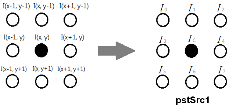
The LBP calculation formula is as illustrated in the following figure.
LBP Calculation Formula for E_MI_IVE_LBP_CHAL_MODE_U8C1 mode:
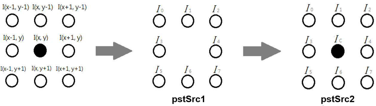
LBP Calculation Formula for E_MI_IVE_LBP_CHAL_MODE_U8C2 mode:
E_MI_IVE_LBP_CMP_NORMAL

E_MI_IVE_LBP_CMP_ABS

E_MI_IVE_LBP_CMP_ABS_MUL

In U8C1 mode, l(x,y) refers to pstSrc1, lpb(x,y) refers to pstDst, and thr refers to pstLbpCtrl→un8BitThr. In U8C2 mode, Ic refers to pstScr2.
1.31. MI_IVE_NormGrad
-
Function
Execute a normalized gradient calculation task, in which the gradient average components are normalized to S8.
-
Syntax
MI_S32 MI_IVE_NormGrad(MI_IVE_HANDLE hHandle,
MI_IVE_SrcImage_t *pstSrc,
MI_IVE_DstImage_t *pstDstH,
MI_IVE_DstImage_t *pstDstV,
MI_IVE_DstImage_t *pstDstHV,
MI_IVE_NormGradCtrl_t *pstNormGradCtrl, MI_BOOL
bInstant);
-
Parameter
Parameter Name Description Input/Output hHandle Regional handle number. Parameter range: [0, MI_IVE_HANDLE_MAX). Input pstSrc Source image pointer. Cannot be null. Input pstDstH Gradient component image H pointer gained by template filtering and normalization to S8. According to pstNormGradCtrl→eOutCtrl, this parameter cannot be null if output is required. Output pstDstV Gradient component image V pointer gained by transposed template filtering and normalization to S8. According to pstNormGradCtrl→eOutCtrl, this parameter cannot be null if output is required. Output pstDstHV Image pointer gained by template and transposed template filtering and normalization to S8. The image pointer is saved in package format. According to pstNormGradCtrl→eOutCtrl, this parameter cannot be null if output is required. Output pstNormGradCtrl Control info pointer. Input bInstant Reserved. Input Parameter Name Supported Image Type Address Alignment Resolution pstSrc U8C1 16 byte 64x64 ~ 1920x1024 pstDstH S8C1 16 byte Same as pstSrc pstDstV S8C1 16 byte Same as pstSrc pstDstHV S8C2_PACKAGE 16 byte Same as pstSrc -
Return Value
Return Value Description 0 Successful. Non-zero Failed. Please refer to ERROR CODE. -
Requirement
-
Header: mi_comm_ive.h, mi_ive.h, mi_ive.h
-
Library: libmi_ive.a
-
-
Note
-
The output modes of the control parameter are as follows:
For E_MI_IVE_NORM_GRAD_OUT_CTRL_HOR_AND_VER, pstDstH and pstDstV pointers cannot be null and the strides thereof should be consistent.
For E_MI_IVE_NORM_GRAD_OUT_CTRL_HOR, pstDstH cannot be null.
For E_MI_IVE_NORM_GRAD_OUT_CTRL_VER, pstDstV cannot be null.
For E_MI_IVE_NORM_GRAD_OUT_CTRL_COMBINE, pstDstHV cannot be null.
-
-
Related API
1.32. MI_IVE_LkOpticalFlow
-
Function
Execute a single layer LK optical flow calculation task.
-
Syntax
MI_S32 MI_IVE_LKOpticalFlow(MI_IVE_HANDLE hHandle,
MI_IVE_SrcImage_t*pstSrcPre,
MI_IVE_SrcImage_t*pstSrcCur,
MI_IVE_SrcMemInfo_t *pstPoint,
MI_IVE_MemInfo_t *pstMv,
MI_IVE_LkOpticalFlowCtrl_t *pstLkOptiFlowCtrl, MI_BOOL
bInstant);
-
Parameter
Parameter Name Description Input/Output hHandle Regional handle number. Parameter range: [0, MI_IVE_HANDLE_MAX). Input pstSrcPre Previous image pointer. Cannot be null. Input pstSrcCur Current image pointer. Cannot be null. Width and height same as pstSrcPre. Input pstPoint Current pyramid layer initial feature point coordinate. Cannot be null. The coordinate can only be of the type MI_IVE_PointS25Q7_t. The memory should at least have the size below: pstLkOptiFlowCtrl→u16CornerNum * sizeof(MI_IVE_PointS25Q7_t). Input pstMv Corresponds to pstPoint feature point motion displacement vector. Cannot be null. The first calculation needs to be initialized to 0 input; the subsequent layer calculation should input the motion displacement vector calculated by the upper layer. The displacement can only be of the type MI_IVE_MvS9Q7_t. The memory should at least have the size below: pstLkOptiFlowCtrl→u16CornerNum * sizeof(MI_IVE_MvS9Q7_t) Input, Output pstLkOptiFlowCtrl Control parameter pointer. Cannot be null. Input bInstant Reserved. Input Parameter Name Supported Image Type Address Alignment Resolution pstSrcPre U8C1 16 byte 64x64 ~ 720x576 pstSrcCur U8C1 16 byte Same as pstSrcPre -
Return Value
Return Value Description 0 Successful. Non-zero Failed. Please refer to ERROR CODE. -
Requirement
-
Header: mi_comm_ive.h, mi_ive.h, mi_ive.h
-
Library: libmi_ive.a
-
-
Note
-
In solving the following optical flow equation, only 7x7 pixels around the feature point are used to calculate the corresponding Ix, Iy, It.
\begin{bmatrix} \sum_{}^{}I_{x}^{2} & \sum_{}^{}{I_{x}I_{y}} \\ \sum_{}^{}{I_{x}I_{y}} & \sum_{}^{}I_{y}^{2} \\ \end{bmatrix}\left\lbrack \frac{u}{\begin{matrix} \ \\ v \\ \ \\ \end{matrix}} \right\rbrack = \left\lbrack \frac{- \sum_{}^{}{I_{x}I_{t}}}{\begin{matrix} \ \\ - \sum_{}^{}{I_{y}I_{t}} \\ \ \\ \end{matrix}} \right\rbrack -
Where, Ix, Iy, It refer respectively to the partial derivation of the current image in the x, y direction and the difference between the current image and the previous image.
-
Let’s take the following 3-layer pyramid LK optical flow calculation as an example. The width and height of the image of each layer must be half the width and height of the image of its upper layer. The calculation method is as shown in the following figure.
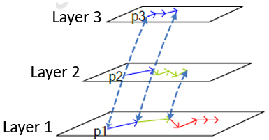
Fig 1-12: 3-Layer Pyramid LK Optical Flow Calculation
According to the input feature point coordinates, the coordinates corresponding to the feature points of the three-layer pyramid are calculated: p0, p1, p2;
Using p2 and mv2, which is initially 0, as input, call the LK operator to find the displacement mv2 on the second layer;
Using p1 and mv2 as input, call the LK operator to find the displacement mv1 on the frist layer;
Using p0 and mv1 as input, call the LK operator to find the displacement mv0 on the zero layer;
If the zero layer is not the original image, the true displacement mv of the LK optical flow can be obtained according to the proportional relationship between the zero layer and the original image.
-
Design and usage restrictions: Each feature point is calculated only by the data of the fixed size window centered on the feature point. If the feature point displacement target point exceeds the fixed size window during the iterative calculation process, the calculation optical flow would fail.
-
1.33. MI_IVE_Sad
-
Function
Calculate 16-bit/8-bit SAD images of 4x4/8x8/16x16 blocks for two images, and threshold output for SAD
-
Syntax
MI_S32 MI_IVE_Sad(MI_IVE_HANDLE hHandle,
MI_IVE_SrcImage_t*pstSrc1,
MI_IVE_SrcImage_t*pstSrc2,
MI_IVE_DstImage_t *pstSad,
MI_IVE_DstImage_t *pstThr,
MI_IVE_SadCtrl_t *pstSadCtrl, MI_BOOL bInstant);
-
Parameter
Parameter Name Description Input/Output hHandle Regional handle number. Parameter range: [0, MI_IVE_HANDLE_MAX). Input pstSrc1 Source image 1 pointer. Cannot be null. Input pstSrc2 Source image 2 pointer. Cannot be null. Width and height same as pstSrc1. Input pstSad Output SAD image pointer. Output pstThr Output SAD thresholding image pointer. According to pstSadCtrl→eOutCtrl, this parameter cannot be null if output is required.
According to pstSadCtrl→eMode, refers to 4x4, 8x8, and 16x16 block modes, the width and height thereof being ¼, ⅛, and 1/16 of pstSrc1 respectively.
According to pstSadCtrl→eOutCtrl, this parameter cannot be null if output is required.
According to pstSadCtrl→eMode, refers to 4x4, 8x8, and 16x16 block modes, the width and height thereof being ¼, ⅛, and 1/16 of pstSrc1 respectively.Output pstSadCtrl Control info pointer. Cannot be null. Input bInstant Reserved. Input Parameter Name Supported Image Type Address Alignment Resolution pstSrc1 U8C1 1 byte 64x64 ~ 1920x1080 pstSrc2 U8C1 1 byte Same as pstSrc1 pstSad U8C1, U16C1 16 byte According to pstSadCtrl→eMode, refers to 4x4, 8x8, and 16x16 block modes, the width and height thereof being ¼, ⅛, and 1/16 of pstSrc1 respectively. pstThr U8C1 16 byte According to pstSadCtrl→eMode, refers to 4x4, 8x8, 16x16 block modes, the width and height thereof being ¼, ⅛, and 1/16 of pstSrc1 respectively. -
Return Value
Return Value Description 0 Successful. Non-zero Failed. Please refer to ERROR CODE. -
Requirement
-
Header: mi_comm_ive.h, mi_ive.h, mi_ive.h
-
Library: libmi_ive.a
-
-
Note
The calculation formula is as follows:
\text{SAD}_{\text{out}}\left( x,y \right) = \sum_{i = 0}^{M - 1}{\sum_{j = 0}^{M - 1}{abs(I_{src1}\left( M*x + i,M*y + j \right) - I_{src2}\left( M*x + i,M*y + j \right))}}\text{Thr}\left( x,y \right) = \left\{ \begin{matrix} minVal\cdots O(x,y) \leq Thresh \\ maxVal\cdots O(x,y) > Thresh \\ \end{matrix} \right.\Where,
I_{src1}refers to pstSrc1,
I_{src2}refers to pstSrc2, SADout(x,y) refers to pstSad; M is related to pstSadCtrl→eMode, and represents 4, 8, and 16 when referring to E_MI_IVE_SAD_MODE_MB_4X4, E_MI_IVE_SAD_MODE_MB_8X8, and E_MI_IVE_SAD_MODE_MB_16X16; THRout(x,y) refers to pstThr; Thr, minVal and maxVal refer respectively to pstSadCtrl→u16Thr, pstSadCtrl→u8MinVal and stSadCtrl→u8MaxVal.
1.34. MI_IVE_Bernsen
-
Function
Execute a Bernsen thresh task for the 3x3 and 5x5 windows.
-
Syntax
MI_S32 MI_IVE_Bernsen(MI_IVE_HANDLE hHandle,
MI_IVE_SrcImage_t *pstSrc,
MI_IVE_DstImage_t *pstDst, MVE_IVE_BernsenCtrl_t *pstBernsenCtrl,MI_BOOL bInstant);
-
Parameter
Parameter Name Description Input/Output hHandle Regional handle number. Parameter range: [0, MI_IVE_HANDLE_MAX). Input pstSrc Source image pointer. Cannot be null. Input pstDst Pointer to the output image template. It cannot be null. The height and width are the same as those of pstSrc. Output pstBernsenCtrl Pointer to the control parameter. It cannot be null. Output bInstant Reserved. Input Parameter Name Supported Image Type Address Alignment Resolution pstSrc U8C1 16 byte 64x64 ~ 1920x1024 pstDst S8C1 16 byte Same as pstSrc -
Return Value
Return Value Description 0 Successful. Non-zero Failed. Please refer to ERROR CODE. -
Requirement
-
Header: mi_comm_ive.h, mi_ive.h, mi_ive.h
-
Library: libmi_ive.a
-
-
Note
Two modes are supported. See MI_IVE_BernsenMode_e for details.
The following are related formulas:
-
MI_BERNSEN_MODE_NORMAL
T(x,y)=0.5*(max_{-\omega\leqslant i\leqslant \omega,-\omega\leqslant j\leqslant \omega}I(x+i,y+j)+min_{-\omega\leqslant i\leqslant \omega,-\omega\leqslant j\leqslant \omega}I(x+i,y+j))I_{out}(x,y)=\left \{ \begin{aligned} 0,I(x,y)< T(x,y) \\ 1,I(x,y)\leqslant T(x,y) \end{aligned} \right.No value needs to be assigned to pstBernsenCtrl->u8Thr.
-
MI_BERNSEN_MODE_THRESH
T(x,y)=0.5*(max_{-\omega\leqslant i\leqslant \omega,-\omega\leqslant j\leqslant \omega}I(x+i,y+j)+min_{-\omega\leqslant i\leqslant \omega,-\omega\leqslant j\leqslant \omega}I(x+i,y+j))I_{out}(x,y)=\left \{ \begin{aligned} 0,I(x,y)< 0.5*T(x,y)+Thr \\ 1,I(x,y)\geqslant 0.5*T(x,y)+Thr \end{aligned} \right.I(x,y) corresponds to pstSrc, Iout(x,y) corresponds to pstDst, and Thr corresponds to u8thr in pstBernsenCtrl.
-
1.35. MI_IVE_LineFilterHor
-
Function
Execute a horizontal density filter task for binary images.
-
Syntax
MI_S32 MI_IVE_LineFilterHor(MI_IVE_HANDLE hHandle,
MI_IVE_SrcImage_t *pstSrcDst,
MVE_IVE_LineFilterHorCtrl_t *pstLineFilterHorCtrl, MI_BOOL bInstant);
-
Parameter
Parameter Name Description Input/Output hHandle Regional handle number. Parameter range: [0, MI_IVE_HANDLE_MAX). Input pstSrcDst Pointer to the source image or the output after processing. It cannot be null. Input / Output pstLineFilterHorCtrl Pointer to the control parameter. It cannot be null. Input bInstant Reserved. Input Parameter Name Supported Image Type Address Alignment Resolution pstSrcDst U8C1 binary image 16 byte 64x64 ~ 1920x1024 -
Return Value
Return Value Description 0 Successful. Non-zero Failed. Please refer to ERROR CODE. -
Requirement
-
Header: mi_comm_ive.h, mi_ive.h, mi_ive.h
-
Library: libmi_ive.a
-
-
Note
The images are counted in the horizontal direction. Each line consists of line segments that appear alternatively (white line segments) and gaps between the line segments (black line segments). The length of a black line segment is satisfied the following condition, the block line segment is set to a white line segment.
The following is the calculation principle:
-
Horizontally scan the binary image, and record the result, as shown in the figure below.
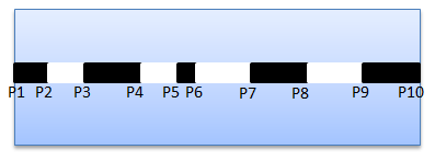
-
Assume the current gap is line_black56, if conform to the condition as below, the black line segment will be set to a white line segment.
Condition 1 : line_black34 > thr1
Condition 2 : line_black78 > thr1
Condition 3 :
(line_white45 + line_black56 + line_white67) <= (line_white45 + line_white67)thr2
Condition 4 : (line_white45 + line_white67) > 1
-
Following these step (step 1 and step 2), until handle the whole binary image. The result is shown in figure below.
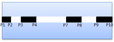
-
Horizontally scan the binary image again. According to the relationship between the white line segment and black line segment, transform the black line segment into the white line segment.
Assume the current gap is line_black34, if conform to the condition as below, the black line segment will be set to a white line segment.
Condition 1 : line_block34 < thr3
Condition 2 : line_white47 > 2thr3
Condition 3 : line_white23 > 9
Condition 4 : line_white23 < 3thr3
-
Following step 3 and step 4, until handle the whole binary image.
-
1.36. MI_IVE_LineFilterVer
-
Function
Execute a vertical density filter task for binary images.
-
Syntax
MI_S32 MI_IVE_LineFilterVer(MI_IVE_HANDLE hHandle,
MI_IVE_SrcImage_t *pstSrcDst,
MVE_IVE_LineFilterVerCtrl_t *pstLineFilterVerCtrl, MI_BOOL bInstant);
-
Parameter
Parameter Name Description Input/Output hHandle Regional handle number. Parameter range: [0, MI_IVE_HANDLE_MAX). Input pstSrcDst Pointer to the source image or the output after processing. It cannot be null. Input / Output pstLineFilterVerCtrl Pointer to the control parameter. It cannot be null. Input bInstant Reserved. Input Parameter Name Supported Image Type Address Alignment Resolution pstSrcDst U8C1 binary image 16 byte 64x64 ~ 1920x1024 -
Return Value
Return Value Description 0 Successful. Non-zero Failed. Please refer to ERROR CODE. -
Requirement
-
Header: mi_comm_ive.h, mi_ive.h, mi_ive.h
-
Library: libmi_ive.a
-
-
Note
The images are counted in the vertical direction. Each line consists of line segments that appear alternatively white line segments and gaps between the line segments (black line segments). The length of a black line segment is satisfied the following condition, the block line segment is set to a white line segment.
The following is the calculation principle:
-
Vertically scan the binary image, and record the result, as shown in the figure below.
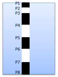
-
Assume the current gap is line_black56, if conform to the condition as below, the black line segment will be set to a white line segment.
Condition 1 : line_black56 < thr
Condition 2 : line_black67 > 6 & line_whitr67 < 25
Condition 3 : line_white45 < 12
-
Following these step (step 1 and step 2), until handle the whole binary image.
-
1.37. MI_IVE_NoiseRemoveHor
-
Function
Execute a horizontal noise removal task for binary images.
-
Syntax
MI_S32 MI_IVE_NoiseRemoveHor(MI_IVE_HANDLE hHandle,
MI_IVE_SrcImage_t *pstSrcDst,
MVE_IVE_NoiseRemoveHorCtrl_t *pstNoiseRemoveHorCtrl, MI_BOOL bInstant);
-
Parameter
Parameter Name Description Input/Output hHandle Regional handle number. Parameter range: [0, MI_IVE_HANDLE_MAX). Input pstSrcDst Pointer to the source image or the output after processing. It cannot be null. Input / Output pstNoiseRemoveHorCtrl Pointer to the control parameter. It cannot be null. Input bInstant Reserved. Input Parameter Name Supported Image Type Address Alignment Resolution pstSrcDst U8C1 binary image 16 byte 64x64 ~ 1920x1024 -
Return Value
Return Value Description 0 Successful. Non-zero Failed. Please refer to ERROR CODE. -
Requirement
-
Header: mi_comm_ive.h, mi_ive.h, mi_ive.h
-
Library: libmi_ive.a
-
-
Note
The images are counted in the horizontal direction. Each line consists of line segments that appear alternatively (white line segments) and gaps between the line segments (black line segments). If the length of a line segment is smaller than the thr1 or bigger than the thr2, convert the line segment into a gap.
1.38. MI_IVE_NoiseRemoveVer
-
Function
Execute a vertical noise removal task for binary images.
-
Syntax
MI_S32 MI_IVE_NoiseRemoveHor(MI_IVE_HANDLE hHandle,
MI_IVE_SrcImage_t *pstSrcDst,
MVE_IVE_NoiseRemoveVerCtrl_t *pstNoiseRemoveVerCtrl, MI_BOOL bInstant);
-
Parameter
Parameter Name Description Input/Output hHandle Regional handle number. Parameter range: [0, MI_IVE_HANDLE_MAX). Input pstSrcDst Pointer to the source image or the output after processing. It cannot be null. Input / Output pstNoiseRemoveVerCtrl Pointer to the control parameter. It cannot be null. Input bInstant Reserved. Input Parameter Name Supported Image Type Address Alignment Resolution pstSrcDst U8C1 binary image 16 byte 64x64 ~ 1920x1024 -
Return Value
Return Value Description 0 Successful. Non-zero Failed. Please refer to ERROR CODE. -
Requirement
-
Header: mi_comm_ive.h, mi_ive.h, mi_ive.h
-
Library: libmi_ive.a
-
-
Note
The images are counted in the vertical direction. Each line consists of line segments that appear alternatively (white line segments) and gaps between the line segments (black line segments). If the length of a line segment is smaller than the thr1 or bigger than the thr2, convert the line segment into a gap.
1.39. MI_IVE_AdpThresh
-
Function
Execute an adaptive thresh task.
-
Syntax
MI_S32 MI_IVE_AdpThresh(MI_IVE_HANDLE hHandle,
MI_IVE_SrcImage_t *pstSrc,
MI_IVE_SrcImage_t *pstInteg,
MI_IVE_DstImage_t *pstDst,
MVE_IVE_AdpThreshCtrl_t *pstAdpThrCtrl,
MI_BOOL bInstant);
-
Parameter
Parameter Name Description Input/Output hHandle Regional handle number. Parameter range: [0, MI_IVE_HANDLE_MAX). Input pstSrc Pointer to the source image or the output after processing. It cannot be null. Input pstInteg Pointer to the integral image of the source image. It cannot be null. Input pstDst Pointer to the target binary image. It cannot be null. Output pstAdpThrCtrl Pointer to the control parameter. It cannot be null. Input bInstant Reserved. Input Parameter Name Supported Image Type Address Alignment Resolution pstSrc U8C1 16 byte 64x64 ~ 1920x1024 pstInteg U32C1 16 byte 64x64 ~ 1920x1024 pstDst U8C1 16 byte 64x64 ~ 1920x1024 -
Return Value
Return Value Description 0 Successful. Non-zero Failed. Please refer to ERROR CODE. -
Requirement
-
Header: mi_comm_ive.h, mi_ive.h, mi_ive.h
-
Library: libmi_ive.a
-
-
Note
The following is the formula:
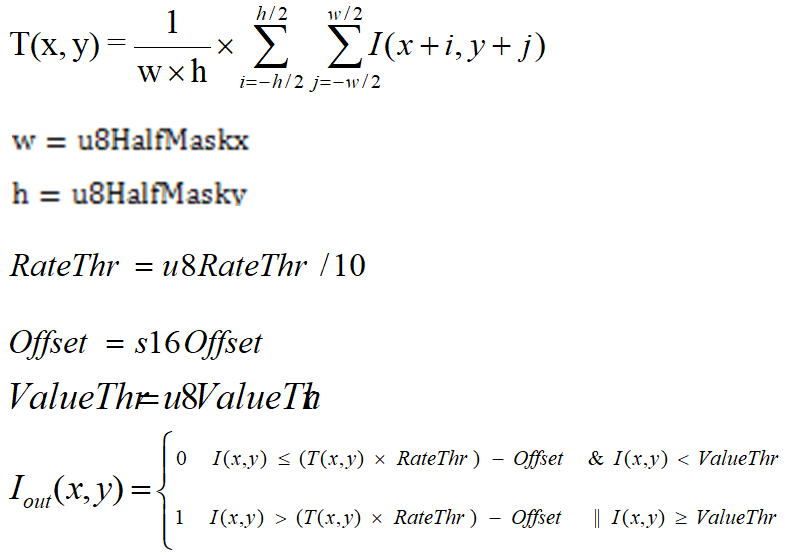
I(x, y) corresponds to pstSrc, Iout(x,y) corresponds to pstDst, W , h , RateThr , 0ffset and ValueThr correspond to u8HalfMaskx , u8HalfMasky , u8RateThr , s16Offset and u8ValueThr in pstAdpThrCtrl. The integrogram pstInteg is adopted to rapidly calculate the area by using:
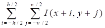
1.40. MI_IVE_Resize
-
Function
Execute an image scaling task.
-
Syntax
MI_S32 MI_IVE_Resize(MI_IVE_HANDLE hHandle,
MI_IVE_SrcImage_t *pstSrc,
MI_IVE_DstImage_t *pstDst,
MVE_IVE_ResizeCtrl_t * pstResizeCtrl, MI_BOOL
bInstant);
-
Parameter
Parameter Name Description Input/Output hHandle Regional handle number. Parameter range: [0, MI_IVE_HANDLE_MAX). Input pstSrc Pointer to the source image or the output after processing. It cannot be null. Input pstDst Pointer to the target binary image. It cannot be null. Output pstResizeCtrl Pointer to the control parameter. It cannot be null. Input bInstant Reserved. Input Parameter Name Supported Image Type Address Alignment Resolution pstSrc U8C1, U8C3_PLANAR, U8C3_PACKAGE and YUV420SP 16 byte 64x64 ~ 1920x1024 pstDst U8C1, U8C3_PLANAR, U8C3_PACKAGE and YUV420SP 16 byte 64x64 ~ 1920x1024 -
Return Value
Return Value Description 0 Successful. Non-zero Failed. Please refer to ERROR CODE. -
Requirement
-
Header: mi_comm_ive.h, mi_ive.h, mi_ive.h
-
Library: libmi_ive.a
-
-
Note
- Resize is implemented by referring to the standard bilinear method.
1.41. MI_IVE_Bat
-
Function
Execute the horizontal or vertical alternating time for binary images.
-
Syntax
MI_S32 MI_IVE_BAT (MI_IVE_HANDLE hHandle,
MI_IVE_SrcImage_t *pstSrc,
MI_IVE_DstMemInfo_t *pstDstH,
MI_IVE_DstMemInfo_t *pstDstV,
MVE_IVE_BatCtrl_t *pstCtrl, MI_BOOL bInstant);
-
Parameter
Parameter Name Description Input/Output hHandle Regional handle number. Parameter range: [0, MI_IVE_HANDLE_MAX). Input pstSrc Pointer to the source image. It cannot be null. Input pstDstH Pointer to the horizontal output image. It cannot be null. Output pstDstV Pointer to the vertical output image. It cannot be null. Output pstCtrl Pointer to the control parameter. It cannot be null. Input bInstant Reserved. Input Parameter Name Supported Image Type Address Alignment Resolution pstSrc U8C1 binary image 16 byte 64x64 ~ 1920x1024 pstDstH U8C1 binary image 16 byte 64x64 ~ 1920x1024 pstDstV U8C1 binary image 16 byte 64x64 ~ 1920x1024 -
Return Value
Return Value Description 0 Successful. Non-zero Failed. Please refer to ERROR CODE. -
Requirement
-
Header: mi_comm_ive.h, mi_ive.h, mi_ive.h
-
Library: libmi_ive.a
-
-
Note
Horizontal(vertical) scan the input binary image, when the adjacent value are found different, the result of horizontal(vertical) alternating time h(v) will plus 1, the final horizontal output O(h) and vertical output O(v) should be as follows :
O(h)=\left\{ \begin{aligned} 1,h\geqslant u16HorTimes \\ 0,h< u16HorTimes \end{aligned} \right.O(v)=\left\{ \begin{aligned} 1,v\geqslant u16HorTimes \\ 0,v< u16HorTimes \end{aligned} \right.
1.42. MI_IVE_Acc
-
Function
Execute an accumulation task for two gray-scale images.
-
Syntax
MI_S32 MI_IVE_Acc (MI_IVE_HANDLE hHandle,
MI_IVE_SrcImage_t * pstSrc0,
MI_IVE_SrcImage_t *pstSrc1,
MI_IVE_DstImage_t *pstDst,
MVE_IVE_AccCtrl_t * pstAccCtrl, MI_BOOL bInstant);
-
Parameter
Parameter Name Description Input/Output hHandle Regional handle number. Parameter range: [0, MI_IVE_HANDLE_MAX). Input pstSrc0 Pointer to the source image or the output after processing. It cannot be null. Input pstSrc1 Pointer to the source image or the output after processing. It cannot be null. Input pstDst Pointer to the target binary image. It cannot be null. Output pstAccCtrl Pointer to the control parameter. It cannot be null. Input bInstant Reserved. Input Parameter Name Supported Image Type Address Alignment Resolution pstSrc0 U8C1 16 byte 64x64 ~ 1920x1024 pstSrc1 U8C1 16 byte 64x64 ~ 1920x1024 pstDst U8C1 16 byte 64x64 ~ 1920x1024 -
Return Value
Return Value Description 0 Successful. Non-zero Failed. Please refer to ERROR CODE. -
Requirement
-
Header: mi_comm_ive.h, mi_ive.h, mi_ive.h
-
Library: libmi_ive.a
-
-
Note
E_MI_IVE_ACC_MODE_INCREASE :
I_{out}(x,y)=I_{src0}(x,y)+I_{src1}(x,y)E_MI_IVE_ACC_MODE_DECREASE :
I_{out}(x,y)=I_{src0}(x,y)-I_{src1}(x,y)E_MI_IVE_ACC_MODE_INCREASE_MAP_255TO1 :
I_{out}(x,y)=I_{src0}(x,y)+(I_{src1}(x,y)\&0x1)
1.43. MI_IVE_Matrix_Transform
-
Function
Execute the operation of matrix multiplication
-
Syntax
MI_S32 MI_IVE_Matrix_Transform(MI_IVE_HANDLE hHandle,
MI_IVE_SrcImage_t *pstSrc1,
MI_IVE_SrcImage_t *pstSrc2,
MI_IVE_SrcImage_t *pstSrc3,
MI_IVE_DstImage_t *pstDst1,
MI_IVE_DstImage_t *pstDst2,
MI_IVE_DstImage_t *pstDst3,
MI_IVE_MatrTranfCtrl_t *pstMatrTranfCtrl, MI_BOOL bInstant);
-
Parameter
Parameter Name Description Input/Output hHandle Regional handle number. Parameter range: [0, MI_IVE_HANDLE_MAX). Input pstSrc1 Pointer to the source image. It cannot be null. Input pstSrc2 Pointer to the source image. It cannot be null. Input pstSrc3 Pointer to the source image. It cannot be null. Input pstDst1 Pointer to the output image. It cannot be null. Output pstDst2 Pointer to the output image. It cannot be null. Output pstDst3 Pointer to the output image. It cannot be null. Output pstMatrTranfCtrl Pointer to the control parameter. It cannot be null. Input bInstant Reserved. Input Parameter Name Supported Image Type Address Alignment Resolution pstSrc1 S32C1 16 byte 64x64 ~ 1920x1024 pstSrc2 S32C1 16 byte 64x64 ~ 1920x1024 pstSrc3 S32C1 16 byte 64x64 ~ 1920x1024 pstDst1 S32C1 16 byte 64x64 ~ 1920x1024 pstDst2 S32C1 16 byte 64x64 ~ 1920x1024 pstDst3 S32C1 16 byte 64x64 ~ 1920x1024 -
Return Value
Return Value Description 0 Successful. Non-zero Failed. Please refer to ERROR CODE. -
Requirement
-
Header: mi_comm_ive.h, mi_ive.h, mi_ive.h
-
Library: libmi_ive.a
-
-
Note
The matrix_transform calculation formula is as illustrated in the following figure.
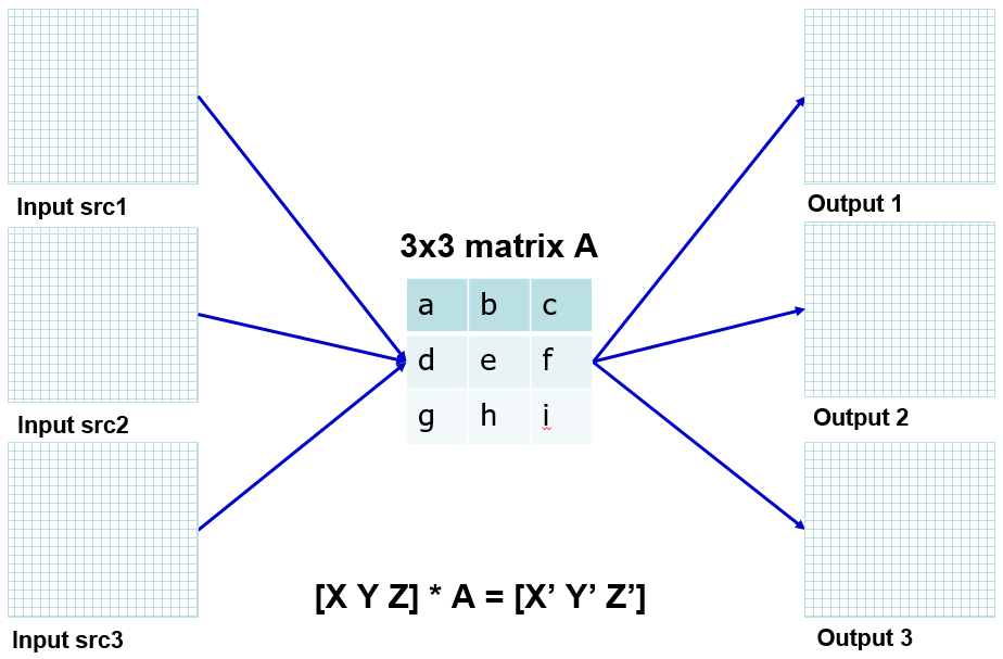
Fig 1-13: Illustration of matrix_transform calculation formula
Each input and output element consists of 16 integer, 15 decimal and 1 sign.
Each input element of matrix consists of 16 integer, 15 decimal and 1 sign.
Ps: For Pudding series chips, each input element of matrix consists of 1 integer, 14 decimal and 1 sign.
Ps: The input type should be S32C1, for the common standard of different chip format.
1.44. MI_IVE_Image_Dot
-
Function
Execute the operation of dot product.
-
Syntax
MI_S32 MI_IVE_ Image_Dot (MI_IVE_HANDLE hHandle,
MI_IVE_SrcImage_t *pstSrc1,
MI_IVE_SrcImage_t *pstSrc2,
MI_IVE_DstImage_t *pstDst, MI_BOOL bInstant);
-
Parameter
Parameter Name Description Input/Output hHandle Regional handle number. Parameter range: [0, MI_IVE_HANDLE_MAX). Input pstSrc1 Pointer to the source image. It cannot be null. Input pstSrc2 Pointer to the source image. It cannot be null. Input pstDst Pointer to the output image. It cannot be null. Output bInstant Reserved. Input Parameter Name Supported Image Type Address Alignment Resolution pstSrc1 S32C1 16 byte 64x64 ~ 1920x1024 pstSrc2 S32C1 16 byte 64x64 ~ 1920x1024 pstDst S32C1 16 byte 64x64 ~ 1920x1024 -
Return Value
Return Value Description 0 Successful. Non-zero Failed. Please refer to ERROR CODE. -
Requirement
-
Header: mi_comm_ive.h, mi_ive.h, mi_ive.h
-
Library: libmi_ive.a
-
-
Note
The calculation formula is as follows:
I_{\text{out}} = I_{src1}(x,y) \times I_{src2}(x,y)Each input and output element consists of 16 integer, 15 decimal and 1 sign.
1.45. MI_IVE_Shift_Detector
-
Function
Execute the operation of object tracking.
-
Syntax
MI_S32 MI_IVE_Shift_Detector(MI_IVE_HANDLE hHandle,
MI_IVE_SrcImage_t *pstSrc1,
MI_IVE_SrcImage_t *pstSrc2,
MI_IVE_DstImage_t MI_IVE_DstImage_t *pstDstX,
MI_IVE_DstImage_t *pstDstY,
MI_IVE_SHIFT_DETECT_CTRL_t *pstCtrl, MI_BOOL bInstant);
-
Parameter
Parameter Name Description Input/Output hHandle Regional handle number. Parameter range: [0, MI_IVE_HANDLE_MAX). Input pstSrc0 Pointer to the first source image. It cannot be null. Input pstSrc1 Pointer to the second source image. It cannot be null. Input pstDstX Pointer to the shift x image. It cannot be null. Output pstDstY Pointer to the shift y image. It cannot be null. Output pstCtrl Pointer to the control parameter It cannot be null. Input bInstant Reserved. Input | Parameter Name | Supported Image Type | Address Alignment | Resolution | | pstSrc1 | U8C1 | 16 byte | 64x64 ~ 1920x1024 | | pstSrc2 | U8C1 | 16 byte | 64x64 ~ 1920x1024 | | pstDstX | U16C1 | 16 byte | 64x64 ~ 1920x1024 | | pstDstY | U16C1 | 16 byte | 64x64 ~ 1920x1024 |
-
Return Value
Return Value Description 0 Successful. Non-zero Failed. Please refer to ERROR CODE. -
Requirement
-
Header: mi_comm_ive.h, mi_ive.h, mi_ive.h
-
Library: libmi_ive.a
-
-
Note
-
Enter two images (Tk and Tk+1) of the same scene but in different time series, and input the positions of Tk target area by controlling data pointer, and the shift detector would output the tracing result of the target area in Tk+1.
-
If enMode = E_MI_IVE_SHIFT_DETECT_MODE_MULTI, the shift detector would divide images into MxN blocks (block size = u16Width x u16Height) and track all objects in each block.
-
If enMode = E_MI_IVE_SHIFT_DETECT_MODE_SINGLE, the shift detector would only track single object on images.
-
1.46. MI_IVE_AlphaBlending
-
Function
Execute an independent weighted addition calculation task against two grayscale images.
-
Syntax
MI_S32 MI_IVE_AlphaBlending (MI_IVE_HANDLE hHandle,
MI_IVE_SrcImage_t *pstSrc1,
MI_IVE_SrcImage_t *pstSrc2,
MI_IVE_SrcImage_t *pstAlpha,
MI_IVE_DstImage_t *pstDst, MI_BOOL bInstant);
-
Parameter
Parameter Name Description Input/Output hHandle Regional handle number. Parameter range: [0, MI_IVE_HANDLE_MAX). Input pstSrc1 Pointer to the source image. It cannot be null. Input pstSrc2 Pointer to the source image. It cannot be null. Input pstAlpha Pointer to the alpha map. It cannot be null. Input pstDst Pointer to the output image. It cannot be null. Output bInstant Reserved. Input Parameter Name Supported Image Type Address Alignment Resolution pstSrc1 U8C1 16 byte 64x64 ~ 1920x1024 pstSrc2 U8C1 16 byte 64x64 ~ 1920x1024 pstAlpha U8C1 16 byte 64x64 ~ 1920x1024 pstDst U8C1 16 byte 64x64 ~ 1920x1024 -
Return Value
Return Value Description 0 Successful. Non-zero Failed. Please refer to ERROR CODE. -
Requirement
-
Header: mi_comm_ive.h, mi_ive.h, mi_ive.h
-
Library: libmi_ive.a
-
-
Note
The calculation formula is as follows:
I_{\text{Out}} = I_{Src1}\left( x,y \right) \times I_{\text{Alpha}}(x,y) + I_{Src2}(x,y) \times (1 - I_{\text{Alpha}}(x,y))
2. DATA TYPE
2.1. Data Type List
The table below lists the data structure definitions of the related IVE data types:
| Data type | Definition |
|---|---|
| MI_IVE_HIST_NUM | Defines histogram statistics bin number |
| MI_IVE_MAP_NUM | Defines number of mapping lookup table entries |
| MI_IVE_MAX_REGION_NUM | Defines maximum number of connected regions |
| MI_IVE_ST_MAX_CORNER_NUM | Defines maximum number of Shi-Tomasi-like corners |
| MI_IVE_MASK_SIZE_5X5 | Defines Mask size |
| MI_IVE_CANNY_STACK_RESERVED_SIZE | Defines Canny Stack Reserved Size |
| MI_IVE_ImageType_e | Defines image types supported by generalized two-dimensional images |
| MI_IVE_Image_t | Defines generalized two-dimensional image information |
| MI_IVE_SrcImage_t | Defines source image |
| MI_IVE_DstImage_t | Defines output image |
| MI_IVE_Data_t | Defines two-dimensional image information in byte unit |
| MI_IVE_SrcData_t | Defines two-dimensional source data information in byte unit |
| MI_IVE_DstData_t | Defines two-dimensional output data information in byte unit |
| MI_IVE_MemInfo_t | Defines one-dimensional data memory information |
| MI_IVE_SrcMemInfo_t | Defines one-dimensional source data |
| MI_IVE_DstMemInfo_t | Defines one-dimensional output data |
| MI_IVE_Length8bit_u | Defines 8-bit data union |
| MI_IVE_PointU16_t | Defines U16 point information structure |
| MI_IVE_PointS25Q7_t | Defines S25Q7 fixed point information structure |
| MI_IVE_Rect_t | Defines U16 rectangle information structure |
| MI_IVE_FilterCtrl_t | Defines template filter control information |
| MI_IVE_CscMode_e | Defines color space conversion mode |
| MI_IVE_CscCtrl_t | Defines color space conversion control information |
| MI_IVE_FilterAndCscCtrl_t | Defines template filter plus color space conversion composite function control information |
| MI_IVE_SobelOutCtrl_e | Defines Sobel output control information |
| MI_IVE_SobelCtrl_t | Defines Sobel edge extraction control information |
| MI_IVE_MagAndAngOutCtrl_e | Defines Canny edge magnitude and angle calculation output format |
| MI_IVE_MagAndAngCtrl_t | Defines Canny edge magnitude and angle calculation control information |
| MI_IVE_DilateCtrl_t | Defines Dilate control information |
| MI_IVE_ErodeCtrl_t | Defines Erode control information |
| MI_IVE_ThreshMode_e | Defines image binarization output format |
| MI_IVE_ThreshCtrl_t | Defines image binarization control information |
| MI_IVE_SubMode_e | Defines image subtraction output format |
| MI_IVE_SubCtrl_t | Defines image subtraction control parameter |
| MI_IVE_IntegOutCtrl_e | Defines integral map output control parameter |
| MI_IVE_IntegCtrl_t | Defines integral map calculation control parameter |
| MI_IVE_ThreshS16Mode_e | Defines 16-bit signed image thresholding mode |
| MI_IVE_ThreshS16Ctrl_t | Defines 16-bit signed image thresholding control parameter |
| MI_IVE_ThreshU16Mode_e: | Defines 16-bit unsigned image thresholding mode |
| MI_IVE_ThreshU16Ctrl_t | Defines 16-bit unsigned image thresholding control parameter |
| MI_IVE_16BitTo8BitMode_e | Defines 16-bit image to 8-bit image conversion mode |
| MI_IVE_16bitTo8BitCtrl_t | Defines 16-bit image to 8-bit image conversion control parameter |
| MI_IVE_OrdStatFilterMode_e | Defines sequential statistic filtering mode |
| MI_IVE_OrdStatFilter_t | Defines sequential statistic filtering control parameter |
| MI_IVE_MapLutMem_t | Defines Map operator lookup table memory information |
| MI_IVE_EqualizeHistCtrlMem_t | Defines histogram equalization auxiliary memory |
| MI_IVE_EqualizeHistCtrl_t | Defines histogram equalization control parameter |
| MI_IVE_AddMode_e | Define the add calculation mode |
| MI_IVE_AddCtrl_t | Defines image weighted addition control parameter |
| MI_IVE_NccDstMem_t | Defines NCC output memory information |
| MI_IVE_Region_t | Defines connected region information |
| MI_IVE_CcBlob_t | Defines connected region label output information |
| MI_IVE_CclMode_e | Defines connected region mode |
| MI_IVE_CclCtrl_t: | Defines connected region label control parameter |
| MI_IVE_GmmCtrl_t | Defines GMM background modelling control parameter |
| MI_IVE_CannyStackSize_t | Defines strong edge point stack size structure in Canny edge first-half calculation |
| MI_IVE_CannyHysEdgeCtrl_t | Defines control parameter in Canny edge first-half calculation |
| MI_IVE_LbpCmpMode_e | Defines LBP calculation comparison mode. |
| MI_IVE_LbpChalMode_e | Define LBP input channel mode |
| MI_IVE_LbpCtrrl_t | Defines LBP texture calculation control parameter |
| MI_IVE_NormGradOutCtrl_e | Defines normalized gradient information calculation task output control enumeration type |
| MI_IVE_NormGradCtrl_t | Defines normalized gradient information calculation control parameter |
| MI_IVE_MvS9Q7_t | Defines displacement structure |
| MI_IVE_LkOpticalFlowCtrl_t | Defines LK optical flow calculation control parameter |
| MI_IVE_SadMode_e | Defines SAD calculation mode |
| MI_IVE_SadOutCtrl_e | Defines SAD output control mode |
| MI_IVE_SadCtrl_t | Defines SAD control parameter |
| MI_IVE_BernsenCtrl_t | Defines Bernsen thresh control parameters. |
| MI_IVE_BernsenMode_e | Defines the Bernsen thresh mode. |
| MI_IVE_LineFilterHorCtrl_t | Defines control parameters for filtering the horizontal density of binary images. |
| MI_IVE_LineFilterVerCtrl_t | Defines control parameters for filtering the vertical density of binary images. |
| MI_IVE_NoiseRemoveHor_t | Defines the horizontal noise removal control parameter for the binary image. |
| MI_IVE_NoiseRemoveVer_t | Defines the vertical noise removal control parameter for the binary image. |
| MI_IVE_AdpThreshCtrl_t | Defines adaptive thresh control parameters. |
| MI_IVE_ResizeCtrl_t | Defines the resize control parameter |
| MI_IVE_ResizeMode_e | Defines the resize input image mode |
| MI_IVE_BatCtrl_t | Defines the bat control parameter |
| MI_IVE_BatMode_e | Defines the bat output control mode |
| MI_IVE_AccCtrl_t | Defines the acc control parameter |
| MI_IVE_AccMode_e | Defines the acc input control mode |
| MI_IVE_MatrTranfMode_e | Defines the input channel mode of matrix transform |
| MI_IVE_MatrTranfCtrlMode_e | Defines the input control mode of matrix transform. |
| MI_IVE_MatrTranfCtrl_t | Defines the control parameters of matrix transform. |
| MI_IVE_SHIFT_DETECT_MODE_e | Defines the shift detector input control mode. |
| MI_IVE_SHIFT_DETECT_CTRL_t | Defines control parameter of the shift detector. |
2.2. Fixed Point Data Type
-
Description
Defines fixed point data type.
-
Definition
typedef unsigned char   MI_U0Q8;
typedef unsigned char   MI_U1Q7;
typedef unsigned char   MI_U5Q3;
typedef unsigned short  MI_U0Q16;
typedef unsigned short  MI_U4Q12;
typedef unsigned short  MI_U6Q10;
typedef unsigned short  MI_U8Q8;
typedef unsigned short  MI_U14Q2;
typedef unsigned short  MI_U12Q4;
typedef short   MI_S14Q2;
typedef short   MI_S9Q7;
typedef unsigned int    MI_U22Q10;
typedef unsigned int    MI_U25Q7;
typedef int MI_S25Q7;
typedef unsigned short  MI_U8Q4F4;  /*8bits unsigned integer, 4bits decimal fraction, 4bits flag bits*/
-
Member
Member Code Description MI_U0Q8 0 bit for the integer part, and 8 bits for the decimal part. Represented in document as UQ0.8. MI_U1Q7 High-order 1-bit unsigned data for the integer part, and low-order 7 bits for the demical part. Represented in document as UQ1.7. MI_U5Q3 High-order 5-bit unsigned data for the integer part, and low-order 3 bits for the demical part. Represented in document as UQ5.3. MI_U0Q16 0 bit for the integer part, and 16 bits for the demical part. Represented in document as UQ0.16. MI_U4Q12 High-order 4-bit unsigned data for the integer part, and low-order 12 bits for the demical part. Represented in document as UQ4.12. MI_U6Q10 High-order 6-bit unsigned data for the integer part, and low-order 10 bits for the demical part. Represented in document as UQ6.10. MI_U8Q8 High-order 8-bit unsigned data for the integer part, and low-order 8 bits for the demical part. Represented in document as UQ8.8. MI_U14Q2 High-order 14-bit unsigned data for the integer part, and low-order 2 bits for the demical part. Represented in document as UQ14.2. MI_U12Q4 High-order 12-bit unsigned data for the integer part, and low-order 4 bits for the demical part. Represented in document as UQ12.4. MI_S14Q2 High-order 14-bit signed data for the integer part, and low-order 2 bits for the demical part. Represented in document as SQ14.2. MI_S9Q7 High-order 9-bit signed data for the integer part, and low-order 7 bits for the demical part. Represented in document as SQ9.7. MI_U22Q10 High-order 22-bit unsigned data for the integer part, and low-order 10 bits for the demical part. Represented in document as UQ22.10. MI_U25Q7 High-order 25-bit unsigned data for the integer part, and low-order 7 bits for the demical part. Represented in document as UQ25.7. MI_S25Q7 High-order 25-bit signed data for the integer part, and low-order 7 bits for the demical part. Represented in document as SQ25.7. MI_U8Q4F4 High-order 8-bit unsigned data for the integer part, middle 4 bits for the demical part, and low-order 4 bits for flagging. Represented in document as UQF8.4.4. -
Note
MI_UxQyFz\MI_SxQy:
-
The number x after the letter U means x bits of unsigned data are used for the integer part.
-
The number x after the letter S means x bits of signed data are used for the integer part.
-
The number y after the letter Q means y bits of data are used for the demical part.
-
The number z after the letter F means z bits are used for flagging.
-
Highest bit on the leftmost side and lowest bit on the rightmost side.
-
2.3. MI_IVE_HIST_NUM
-
Description
Defines histogram statistics bin number.
-
Definition
#define MI_IVE_HIST_NUM 256
2.4. MI_IVE_MAP_NUM
-
Description
Defines number of mapping lookup table entries.
-
Definition
#define MI_IVE_MAP_NUM 256
2.5. MI_IVE_MAX_REGION_NUM
-
Description
Defines maximum number of connected regions.
-
Definition
#define MI_IVE_MAX_REGION_NUM 255
2.6. MI_IVE_ST_MAX_CORNER_NUM
-
Description
Defines maximum number of Shi-Tomasi-like corners.
-
Definition
#define MI_IVE_ST_MAX_CORNER_NUM 200
2.7. MI_IVE_MASK_SIZE_5X5
-
Description
Defines mask size.
-
Definition
#define MI_IVE_MASK_SIZE_5X5 25
2.8. MI_IVE_CANNY_STACK_RESERVED_SIZE
-
Description
Defines Canny stack reserved size.
-
Definition
#define MI_IVE_CANNY_STACK_RESERVED_SIZE 12
2.9. MI_IVE_ImageType_e
-
Description
Defines image types supported by generalized two-dimensional images.
-
Definition
typedef enum { E_MI_IVE_IMAGE_TYPE_U8C1 =0x0, E_MI_IVE_IMAGE_TYPE_S8C1 =0x1, E_MI_IVE_IMAGE_TYPE_YUV420SP =0x2, /*YUV420 SemiPlanar*/ E_MI_IVE_IMAGE_TYPE_YUV422SP =0x3, /*YUV422 SemiPlanar*/ E_MI_IVE_IMAGE_TYPE_YUV420P =0x4, /*YUV420 Planar*/ E_MI_IVE_IMAGE_TYPE_YUV422P =0x5, /*YUV422 planar*/ E_MI_IVE_IMAGE_TYPE_S8C2_PACKAGE =0x6, E_MI_IVE_IMAGE_TYPE_S8C2_PLANAR =0x7, E_MI_IVE_IMAGE_TYPE_S16C1 =0x8, E_MI_IVE_IMAGE_TYPE_U16C1 =0x9, E_MI_IVE_IMAGE_TYPE_U8C3_PACKAGE =0xa, E_MI_IVE_IMAGE_TYPE_U8C3_PLANAR =0xb, E_MI_IVE_IMAGE_TYPE_S32C1 =0xc, E_MI_IVE_IMAGE_TYPE_U32C1 =0xd, E_MI_IVE_IMAGE_TYPE_S64C1 =0xe, E_MI_IVE_IMAGE_TYPE_U64C1 =0xf, E_MI_IVE_IMAGE_TYPE_BUTT }MI_IVE_ImageType_e; -
Member
Member Code Description E_MI_IVE_IMAGE_TYPE_U8C1 Single-channel image, in which each pixel is represented by one 8-bit unsigned data entry. E_MI_IVE_IMAGE_TYPE_S8C1 Single-channel image, in which each pixel is represented by one 8-bit signed data entry. E_MI_IVE_IMAGE_TYPE_YUV420SP Image in YUV420 semiplanar format. E_MI_IVE_IMAGE_TYPE_YUV422SP Image in YUV422 semiplanar format. E_MI_IVE_IMAGE_TYPE_YUV420P Image in YUV420 planar format. E_MI_IVE_IMAGE_TYPE_YUV422P Image in YUV422 planar format. E_MI_IVE_IMAGE_TYPE_S8C2_PACKAGE Dual-channel image in package format, in which each pixel is represented by two 8-bit signed data entries. E_MI_IVE_IMAGE_TYPE_S8C2_PLANAR Dual-channel image in planar format, in which each pixel is represented by two 8-bit signed data entries. E_MI_IVE_IMAGE_TYPE_S16C1 Single-channel image, in which each pixel is represented by one 16-bit signed data entry. E_MI_IVE_IMAGE_TYPE_U16C1 Single-channel image, in which each pixel is represented by one 16-bit unsigned data entry. E_MI_IVE_IMAGE_TYPE_U8C3_PACKAGE 3-channel image in package format, in which each pixel is represented by three 8-bit unsigned data entries. E_MI_IVE_IMAGE_TYPE_U8C3_PLANAR 3-channel image in planar format, in which each pixel is represented by three 8-bit unsigned data entries. E_MI_IVE_IMAGE_TYPE_S32C1 Single-channel image, in which each pixel is represented by one 32-bit signed data entry. E_MI_IVE_IMAGE_TYPE_U32C1 Single-channel image, in which each pixel is represented by one 32-bit unsigned data entry. E_MI_IVE_IMAGE_TYPE_S64C1 Single-channel image, in which each pixel is represented by one 64-bit signed data entry. E_MI_IVE_IMAGE_TYPE_U64C1 Single-channel image, in which each pixel is represented by one 64-bit unsigned data entry. -
Related Data Type and Interface
2.10. MI_IVE_Image_t
-
Description
Defines generalized two-dimensional image information.
-
Definition
typedef struct MI_IVE_Image_s { MI_IVE_ImageType_e eType; MI_PHY aphyPhyAddr[3]; MI_U8 *apu8VirAddr[3]; MI_U16 au16Stride[3]; MI_U16 u16Width; MI_U16 u16Height; MI_U16 u16Reserved; /*Can be used such as elemSize*/ }MI_IVE_Image_t; -
Member
Member Code Description enType Generalized image type. aphyPhyAddr[3] Generalized image physical address array. apu8VirAddr[3] Generalized image virtual address array. au16Stride[3] Generalized image stride. u16Width Generalized image width. u16Height Generalized image height. u16Reserved Mark the memory as being used by software or hardware to determine the operation of automatic Cache Invalidate and Cache Flush. -
Note
-
Different operators have different requirements as to the alignment of image input/output address.
-
u16Width, u16Height and u16Stride are all in pixel unit.
-
-
Related Data Type and Interface
2.11. MI_IVE_SrcImage_t
-
Description
Defines source image.
-
Definition
typedef MI_IVE_Image_t MI_IVE_SrcImage_t;
-
Related Data Type and Interface
2.12. MI_IVE_DstImage_t
-
Description
Defines output image.
-
Definition
typedef MI_IVE_Image_t MI_IVE_DstImage_t;
-
Related Data Type and Interface
MI_IVE_Image_t
MI_IVE_SrcImage_t
2.13. MI_IVE_Data_t
-
Description
Defines two-dimensional data information in byte unit.
-
Definition
typedef struct MI_IVE_Data_s { MI_PHY phyPhyAddr; /*Physical address of the data*/ MI_U8 *pu8VirAddr; MI_U16 u16Stride; /*Data stride by byte*/ MI_U16 u16Height; /*Data height by byte*/ MI_U16 u16Width; /*Data width by byte*/ MI_U16 u16Reserved; }MI_IVE_Data_t; -
Member
Member Code Description phyPhyAddr Image physical address. pu8VirAddr Image virtual address. u16Stride Image stride. u16Height Image width. u16Width Image height. u16Reserved Reserved. -
Note
Represents two-dimensional data in byte unit; can be converted with MI_IVE_Image_t image.
2.14. MI_IVE_SrcData_t
-
Description
Defines two-dimensional source data information in byte unit
-
Definition
typedef MI_IVE_Data_t MI_IVE_SrcData_t;
-
Related Data Type and Interface
MI_IVE_Image_t
MI_IVE_DstData_t
2.15. MI_IVE_DstData_t
-
Description
Defines two-dimensional output data information in byte unit.
-
Definition
typedef MI_IVE_Data_t MI_IVE_DstData_t;
-
Related Data Type and Interface
2.16. MI_IVE_MemInfo_t
-
Description
Defines one-dimensional data memory information.
-
Definition
typedef struct MI_IVE_MemInfo_s { MI_PHY phyPhyAddr; MI_U8 *pu8VirAddr; MI_U32 u32Size; }MI_IVE_MemInfo_t; -
Member
Member Code Description phyPhyAddr One-dimensional data physical address. pu8VirAddr One-dimensional data virtual address. u32Size One-dimensional data byte size. -
Related Data Type and Interface
2.17. MI_IVE_SrcMemInfo_t
-
Description
Defines one-dimensional source data.
-
Definition
typedef MI_IVE_MemInfo_t MI_IVE_SrcMemInfo_t;
-
Related Data Type and Interface
2.18. MI_IVE_DstMemInfo_t
-
Description
Defines one-dimensional output data.
-
Definition
typedef MI_IVE_MemInfo_t MI_IVE_DstMemInfo_t;
-
Related Data Type and Interface
2.19. MI_IVE_Length8bit_u
-
Description
Defines 8-bit data union.
-
Definition
typedef union { MI_S8 s8Val; MI_U8 u8Val; } MI_IVE_Length8bit_u; -
Member
Member Code Description s8Val Signed 8-bit value. u8Val Unsigned 8-bit value.
2.20. MI_IVE_PointU16_t
-
Description
Defines U16 point information structure.
-
Definition
typedef struct MI_IVE_PointU16_s { MI_U16 u16X; MI_U16 u16Y; }MI_IVE_PointU16_t; -
Member
Member Code Description u16X x coordinate of point. u16Y y coordinate of point.
2.21. MI_IVE_PointS25Q7_t
-
Description
Defines S25Q7 fixed-point information structure.
-
Definition
typedef struct MI_IVE_PointS25Q7_s { MI_S25Q7 s25q7X; /*X coordinate*/ MI_S25Q7 s25q7Y; /*Y coordinate*/ }MI_IVE_PointS25Q7_t; -
Member
Member Code Description s25q7X x coordinate of point, in SQ25.7 representation. s25q7Y y coordinate of point, in SQ25.7 representation.
2.22. MI_IVE_Rect_t
-
Description
Defines U16 rectangle information structure.
-
Definition
typedef struct MI_IVE_Rect_s { MI_U16 u16X; MI_U16 u16Y; MI_U16 u16Width; MI_U16 u16Height; }MI_IVE_Rect_t; -
Member
Member Code Description u16X X coordinate of the rectangle closest to the coordinate origin. u16Y Y coordinate of the rectangle closest to the coordinate origin. u16Width Width of rectangle. u16Height Height of rectangle.
2.23. MI_IVE_FilterCtrl_t
-
Description
Defines template filter control information.
-
Defines typedef struct MI_IVE_FilterCtrl_s { MI_S8 as8Mask[MI_IVE_MASK_SIZE_5X5]; /*Template parameter filter coefficient*/ MI_U8 u8Norm; /*Normalization parameter, by right shift*/ }MI_IVE_FilterCtrl_t; -
Member
Member Code Description as8Mask[MI_IVE_MASK_SIZE_5X5] 5x5 template coefficient. Setting the peripheral coefficient to 0 can realize a 3x3 template filter. u8Norm Normalization parameter. Parameter range: [0, 13]. -
Note
By configuring different template coefficients, you can obtain different filter effects.
2.24. MI_IVE_CscMode_e
-
Description
Defines color space conversion mode.
-
Definition
typedef enum { E_MI_IVE_CSC_MODE_PIC_BT601_YUV2RGB = 0x0, E_MI_IVE_CSC_MODE_PIC_BT601_YUV2BGR = 0x1, E_MI_IVE_CSC_MODE_PIC_BT601_RGB2YUV = 0x2, E_MI_IVE_CSC_MODE_PIC_BT601_BGR2YUV = 0x3, E_MI_IVE_CSC_MODE_PIC_BT601_NV21_YUV2RGB = 0x4, E_MI_IVE_CSC_MODE_PIC_BT601_NV21_YUV2BGR = 0x5, E_MI_IVE_CSC_MODE_PIC_BT601_RGB2YUV_NV21 = 0x6, E_MI_IVE_CSC_MODE_PIC_BT601_BGR2YUV_NV21 = 0x7, E_MI_IVE_CSC_MODE_MAX }MI_IVE_CscMode_e; -
Member
Member Code Description E_MI_IVE_CSC_MODE_PIC_BT601_YUV2RGB YUV(NV12)2RGB image conversion. E_MI_IVE_CSC_MODE_PIC_BT601_YUV2BGR YUV(NV12)2BGR image conversion. E_MI_IVE_CSC_MODE_PIC_BT601_RGB2YUV RGB2YUV(NV12) image conversion. E_MI_IVE_CSC_MODE_PIC_BT601_BGR2YUV BGR2YUV(NV12) image conversion. E_MI_IVE_CSC_MODE_PIC_BT601_NV21_YUV2RGB YUV(NV21)2RGB image conversion. E_MI_IVE_CSC_MODE_PIC_BT601_NV21_YUV2BGR YUV(NV21)2BGR image conversion. E_MI_IVE_CSC_MODE_PIC_BT601_RGB2YUV_NV21 RGB2YUV(NV21) image conversion. E_MI_IVE_CSC_MODE_PIC_BT601_BGR2YUV_NV21 BGR2YUV(NV21) image conversion. -
Note
-
Input and output data must satisfy 0≤Y, U, V≤255.
-
Input and output data must satisfy 0≤R, G, B≤255.
-
-
Related Data Type and Interface
2.25. MI_IVE_CscCtrl_t
-
Description
Defines color space conversion control information.
-
Definition
typedef struct MI_IVE_CscCtrl_s { MI_IVE_CscMode_e enMode; /*Working mode*/ }MI_IVE_CscCtrl_t; -
Member
Member Code Description enMode Work mode. -
Related Data Type and Interface
2.26. MI_IVE_FilterAndCscCtrl_t
-
Description
Defines template filter plus color space conversion composite function control information.
-
Defines typedef struct MI_IVE_FilterAndCscCtrl_s { MI_IVE_CscMode_e eMode; /*CSC working mode*/ MI_S8 as8Mask[MI_IVE_MASK_SIZE_5X5]; /*Template parameter filter coefficient*/ MI_U8 u8Norm; /*Normalization parameter, by right shift*/ }MI_IVE_FilterAndCscCtrl_t; -
Member
Member Code Description eMode Work mode. as8Mask[MI_IVE_MASK_SIZE_5X5] 5x5 template coefficient. u8Norm Normalization parameter. Parameter range: [0, 13]. -
Note
Only 4 modes of YUV2RGB are supported.
-
Related Data Type and Interface
2.27. MI_IVE_SobelOutCtrl_e
-
Description
Defines Sobel Output control information.
-
Definition
typedef enum { E_MI_IVE_SOBEL_OUT_CTRL_BOTH = 0x0, /*Output horizontal and vertical*/ E_MI_IVE_SOBEL_OUT_CTRL_HOR = 0x1, /*Output horizontal*/ E_MI_IVE_SOBEL_OUT_CTRL_VER = 0x2, /*Output vertical*/ E_MI_IVE_SOBEL_OUT_CTRL_BUTT }MI_IVE_SobelOutCtrl_e; -
Member
Member Code Description E_MI_IVE_SOBEL_OUT_CTRL_BOTH Output results of both template filtering and transposed template filtering. E_MI_IVE_SOBEL_OUT_CTRL_HOR Output template filtering results only. E_MI_IVE_SOBEL_OUT_CTRL_VER Output transposed template filtering results only. -
Related Data Type and Interface
2.28. MI_IVE_SobelCtrl_t
-
Description
Defines Sobel-like gradient calculation control information.
-
Definition
typedef struct MI_IVE_SobelCtrl_s { MI_IVE_SobelOutCtrl_e eOutCtrl; /*Output format*/ MI_S8 as8Mask[MI_IVE_MASK_SIZE_5X5]; /*Template parameter*/ }MI_IVE_SobelCtrl_t; -
Member
Member Code Description eOutCtrl Output control enumeration parameter. as8Mask[MI_IVE_MASK_SIZE_5X5] 5x5 template coefficient. -
Related Data Type and Interface
2.29. MI_IVE_MagAndAngOutCtrl_e
-
Description
Defines gradient magnitude and angle calculation output format.
-
Definition
typedef enum { E_MI_IVE_MAG_AND_ANG_OUT_CTRL_MAG = 0x0, E_MI_IVE_MAG_AND_ANG_OUT_CTRL_MAG_AND_ANG = 0x1, E_MI_IVE_MAG_AND_ANG_OUT_CTRL_BUTT }MI_IVE_MagAndAngOutCtrl_e; -
Member
Member Code Description E_MI_IVE_MAG_AND_ANG_OUT_CTRL_MAG Output magnitude only. E_MI_IVE_MAG_AND_ANG_OUT_CTRL_MAG_AND_ANG Output both magnitude and angle. -
Related Data Type and Interface
2.30. MI_IVE_MagAndAngCtrl_t
-
Description
Defines gradient magnitude and angle calculation control information.
-
Definition
typedef struct MI_IVE_MagAndAngCtrl_s { MI_IVE_MagAndAngOutCtrl_e eOutCtrl; MI_U16 u16Thr; MI_S8 as8Mask[MI_IVE_MASK_SIZE_5X5]; /*Template parameter.*/ }MI_IVE_MagAndAngCtrl_t; -
Member
Member Code Description eOutCtrl Output format. u16Thr Threshold value for magnitude thresholding. as8Mask[MI_IVE_MASK_SIZE_5X5] 5x5 template coefficient. -
Related Data Type and Interface
2.31. MI_IVE_DilateCtrl_t
-
Description
Defines Dilate control information.
-
Definition
typedef struct MI_IVE_DilateCtrl_s { MI_U8 au8Mask[MI_IVE_MASK_SIZE_5X5]; /*The template parameter value must be 0 or 255.*/ }MI_IVE_DilateCtrl_t; -
Member
Member Code Description au8Mask[MI_IVE_MASK_SIZE_5X5] 5x5 template coefficient. Range: 0 or 255.
2.32. MI_IVE_ErodeCtrl_t
-
Description
Defines Erode control information.
-
Definition
typedef struct MI_IVE_ErodeCtrl_s { MI_U8 au8Mask[MI_IVE_MASK_SIZE_5X5]; /*The template parameter value must be 0 or 255.*/ }MI_IVE_ErodeCtrl_t; -
Member
Member Code Description au8Mask[MI_IVE_MASK_SIZE_5X5] 5x5 template coefficient. Range: 0 or 255.
2.33. MI_IVE_ThreshMode_e
-
Description
Defines image binarization output format.
-
Definition
typedef enum { E_MI_IVE_THRESH_MODE_BINARY = 0x0, /*srcVal <= lowThr, dstVal = minVal; srcVal > lowThr, dstVal = maxVal.*/ E_MI_IVE_THRESH_MODE_TRUNC = 0x1, /*srcVal <= lowThr, dstVal = srcVal; srcVal > lowThr, dstVal = maxVal.*/ E_MI_IVE_THRESH_MODE_TO_MINVAL = 0x2, /*srcVal <= lowThr, dstVal = minVal; srcVal > lowThr, dstVal = srcVal.*/ E_MI_IVE_THRESH_MODE_MIN_MID_MAX = 0x3, /*srcVal <= lowThr, dstVal = minVal; lowThr < srcVal <= highThr, dstVal = midVal; srcVal > highThr, dstVal = maxVal.*/ E_MI_IVE_THRESH_MODE_ORI_MID_MAX = 0x4, /*srcVal <= lowThr, dstVal = srcVal; lowThr < srcVal <= highThr, dstVal = midVal; srcVal > highThr, dstVal = maxVal.*/ E_MI_IVE_THRESH_MODE_MIN_MID_ORI = 0x5, /*srcVal <= lowThr, dstVal = minVal; lowThr < srcVal <= highThr, dstVal = midVal; srcVal > highThr, dstVal = srcVal.*/ E_MI_IVE_THRESH_MODE_MIN_ORI_MAX = 0x6, /*srcVal <= lowThr, dstVal = minVal; lowThr < srcVal <= highThr, dstVal = srcVal; srcVal > highThr, dstVal = maxVal.*/ E_MI_IVE_THRESH_MODE_ORI_MID_ORI = 0x7, /*srcVal <= lowThr, dstVal = srcVal; lowThr < srcVal <= highThr, dstVal = midVal; srcVal > highThr, dstVal = srcVal.*/ E_MI_IVE_THRESH_MODE_BUTT }MI_IVE_ThreshMode_e; -
Member
Member Code Description E_MI_IVE_THRESH_MODE_BINARY srcVal ≤ lowThr, dstVal = minVal; srcVal > lowThr, dstVal = maxVal. E_MI_IVE_THRESH_MODE_TRUNC srcVal ≤ lowThr, dstVal = srcVal; srcVal > lowThr, dstVal = maxVal. E_MI_IVE_THRESH_MODE_TO_MINVAL srcVal ≤lowThr, dstVal = minVal; srcVal > lowThr, dstVal = srcVal. E_MI_IVE_THRESH_MODE_MIN_MID_MAX srcVal ≤ lowThr, dstVal = minVal; lowThr < srcVal ≤ highThr, dstVal = midVal; srcVal > highThr, dstVal = maxVal. E_MI_IVE_THRESH_MODE_ORI_MID_MAX srcVal ≤lowThr, dstVal = srcVal; lowThr < srcVal ≤ highThr, dstVal = midVal; srcVal > highThr, dstVal = maxVal. E_MI_IVE_THRESH_MODE_MIN_MID_ORI srcVal ≤lowThr, dstVal = minVal; lowThr < srcVal ≤highThr,dstVal = midVal; srcVal > highThr, dstVal = srcVal. E_MI_IVE_THRESH_MODE_MIN_ORI_MAX srcVal ≤ lowThr, dstVal = minVal; lowThr < srcVal ≤ highThr,dstVal = srcVal; srcVal > highThr, dstVal = maxVal. E_MI_IVE_THRESH_MODE_ORI_MID_ORI srcVal≤ lowThr, dstVal = srcVal; lowThr < srcVal ≤ highThr, dstVal = midVal; srcVal > highThr, dstVal = srcVal. -
Note
For calculation formula, please refer to the Note provided with respect to MI_IVE_Thresh.
-
Related Data Type and Interface
2.34. MI_IVE_ThreshCtrl_t
-
Description
Defines image binarization control information.
-
Definition
typedef struct MI_IVE_ThreshCtrl_s { MI_IVE_ThreshMode_e eMode; MI_U8 u8LowThr; /*user-defined threshold, 0<=u8LowThr<=255 */ MI_U8 u8HighThr; /*user-defined threshold, if eMode<E_MI_IVE_THRESH_MODE_MIN_MID_MAX, u8HighThr is not used, else 0<=u8LowThr<=u8HighThr<=255;*/ MI_U8 u8MinVal; /*Minimum value when tri-level thresholding*/ MI_U8 u8MidVal; /*Middle value when tri-level thresholding, if eMode<2, u32MidVal is not used; */ MI_U8 u8MaxVal; /*Maxmum value when tri-level thresholding*/ }MI_IVE_ThreshCtrl_t; -
Member
Member Code Description eMode Thresholding operation mode. u8LowThresh Low threshold. Parameter range: [0,255]. u8HighThresh High threshold. 0≤u8LowThresh≤u8HighThresh≤255. u8MinVal Min. value. Parameter range: [0,255]. u8MidVal Median value. Parameter range: [0,255]. u8MaxVal Max. value. Parameter range: [0,255]. -
Related Data Type and Interface
2.35. MI_IVE_SubMode_e
-
Description
Defines image subtraction output format.
-
Definition
typedef enum { E_MI_IVE_SUB_MODE_ABS = 0x0, /*Absolute value of the difference*/ E_MI_IVE_SUB_MODE_SHIFT = 0x1, /*The output result is obtained by shifting the result one digit right to reserve the signed bit.*/ E_MI_IVE_SUB_MODE_BUTT }MI_IVE_SubMode_e; -
Member
Member Code Description E_MI_IVE_SUB_MODE_ABS Absolute value of the difference. E_MI_IVE_SUB_MODE_SHIFT Output the result by right-shifting one bit, sign bit reserved. -
Related Data Type and Interface
2.36. MI_IVE_SubCtrl_t
-
Description
Defines image subtraction control parameter.
-
Definition
typedef struct MI_IVE_SubCtrl_s { MI_IVE_SubMode_e eMode; }MI_IVE_SubCtrl_t; -
Member
Member Code Description eMode Image subtraction mode. -
Related Data Type and Interface
2.37. MI_IVE_IntegOutCtrl_e
-
Description
Defines integral map output control parameter.
-
Definition
typedef enum { E_MI_IVE_INTEG_OUT_CTRL_COMBINE = 0x0, E_MI_IVE_INTEG_OUT_CTRL_SUM = 0x1, E_MI_IVE_INTEG_OUT_CTRL_SQSUM = 0x2, E_MI_IVE_INTEG_OUT_CTRL_BUTT }MI_IVE_IntegOutCtrl_e; -
Member
Member Code Description E_MI_IVE_INTEG_OUT_CTRL_COMBINE Output integral map sum and sum of square. E_MI_IVE_INTEG_OUT_CTRL_SUM Output integral map sum only. E_MI_IVE_INTEG_OUT_CTRL_SQSUM Output integral map sum of square only. -
Related Data Type and Interface
2.38. MI_IVE_IntegCtrl_t
-
Description
Defines integral map calculation control parameter.
-
Definition
typedef struct MI_IVE_IntegCtrl_s { MI_IVE_IntegOutCtrl_e eOutCtrl; }MI_IVE_IntegCtrl_t; -
Member
Member Code Description eOutCtrl Integral map output control parameter. -
Related Data Type and Interface
2.39. MI_IVE_ThreshS16Mode_e
-
Description
Defines 16-bit signed image thresholding mode.
-
Definition
typedef enum { E_MI_IVE_THRESH_S16_MODE_S16_TO_S8_MIN_MID_MAX = 0x0, E_MI_IVE_THRESH_S16_MODE_S16_TO_S8_MIN_ORI_MAX = 0x1, E_MI_IVE_THRESH_S16_MODE_S16_TO_U8_MIN_MID_MAX = 0x2, E_MI_IVE_THRESH_S16_MODE_S16_TO_U8_MIN_ORI_MAX = 0x3, E_MI_IVE_THRESH_S16_MODE_BUTT }MI_IVE_ThreshS16Mode_e; -
Member
Member Code Description E_MI_IVE_THRESH_S16_MODE_S16_ TO_S8_MIN_MID_MAX srcVal ≤ lowThr, dstVal = minVal; lowThr < srcVal ≤highThr, dstVal = idVal; srcVal > highThr, dstVal = maxVal; E_MI_IVE_THRESH_S16_MODE_S16_ TO_S8_MIN_ORI_MAX srcVal ≤ lowThr, dstVal = minVal; lowThr < srcVal ≤highThr, dstVal = rcVal; srcVal > highThr, dstVal = maxVal; E_MI_IVE_THRESH_S16_MODE_S16_ TO_U8_MIN_MID_MAX srcVal ≤ lowThr, dstVal = minVal; lowThr < srcVal ≤highThr, dstVal = idVal; srcVal > highThr, dstVal = maxVal; E_MI_IVE_THRESH_S16_MODE_S16_ TO_U8_MIN_ORI_MAX srcVal ≤ lowThr, dstVal = minVal; lowThr < srcVal ≤highThr, dstVal = rcVal; srcVal > highThr, dstVal = maxVal; -
Note
For calculation formula, please refer to the Note provided with respect to MI_IVE_ThreshS16.
-
Related Data Type and Interface
MI_IVE_ThreshS16Ctrl_t
2.40. MI_IVE_ThreshS16Ctrl_t
-
Description
Defines 16-bit signed image thresholding control parameter.
-
Definition
typedef struct MI_IVE_ThreshS16Ctrl_s { MI_IVE_ThreshS16Mode_e eMode; MI_S16 s16LowThr; /*user-defined threshold*/ MI_S16 s16HighThr; /*user-defined threshold*/ MI_IVE_Length8bit_u un8MinVal; /*Minimum value when tri-level thresholding*/ MI_IVE_Length8bit_u un8MidVal; /*Middle value when tri-level thresholding*/ MI_IVE_Length8bit_u un8MaxVal; /*Maxmum value when tri-level thresholding*/ }MI_IVE_ThreshS16Ctrl_t; -
Member
Member Code Description eMode Thresholding operation mode. s16LowThr Low threshold. s16HighThr High threshold. un8MinVal Min. value. un8MidVal Median value. un8MaxVal Max. value. -
Note
For calculation formula, please refer to the Note provided with respect to MI_IVE_ThreshS16.
-
Related Data Type and Interface
2.41. MI_IVE_ThreshU16Mode_e
-
Description
Defines 16-bit unsigned image thresholding mode.
-
Definition
typedef enum { E_MI_IVE_THRESH_U16_MODE_U16_TO_U8_MIN_MID_MAX = 0x0, E_MI_IVE_THRESH_U16_MODE_U16_TO_U8_MIN_ORI_MAX = 0x1, E_MI_IVE_THRESH_U16_MODE_BUTT }MI_IVE_ThreshU16Mode_e; -
Member
Member Code Description E_MI_IVE_THRESH_U16_MODE_U16_ TO_U8_MIN_MID_MAX srcVal ≤ lowThr, dstVal = minVal; lowThr < srcVal ≤highThr, dstVal = midVal; srcVal > highThr, dstVal = maxVal; E_MI_IVE_THRESH_U16_MODE_U16_ TO_U8_MIN_ORI_MAX srcVal ≤ lowThr, dstVal = minVal; lowThr < srcVal ≤highThr, dstVal = srcVal; srcVal > highThr, dstVal = maxVal; -
Note
For calculation formula, please refer to the Note provided with respect to MI_IVE_ThreshU16.
-
Related Data Type and Interface
2.42. MI_IVE_ThreshU16Ctrl_t
-
Description
Defines 16-bit unsigned image thresholding control parameter.
-
Definition
typedef struct MI_IVE_ThreshU16Ctrl_s { MI_IVE_ThreshU16Mode_e eMode; MI_U16 u16LowThr; MI_U16 u16HighThr; MI_U8 u8MinVal; MI_U8 u8MidVal; MI_U8 u8MaxVal; }MI_IVE_ThreshU16Ctrl_t; -
Member
Member Code Description eMode Thresholding operation mode. u16LowThr Low threshold. u16HighThr High threshold. u8MinVal Min. value. Parameter range: [0,255]. u8MidVal Median value. Parameter range: [0,255]. u8MaxVal Max. value. Parameter range: [0,255]. -
Note
For calculation formula, please refer to the Note provided with respect to MI_IVE_ThreshU16.
-
Related Data Type and Interface
2.43. MI_IVE_16BitTo8BitMode_e
-
Description
Defines 16-bit image data to 8-bit image data conversion mode.
-
Definition
typedef enum { E_MI_IVE_16BIT_TO_8BIT_MODE_S16_TO_S8 = 0x0, E_MI_IVE_16BIT_TO_8BIT_MODE_S16_TO_U8_ABS = 0x1, E_MI_IVE_16BIT_TO_8BIT_MODE_S16_TO_U8_BIAS = 0x2, E_MI_IVE_16BIT_TO_8BIT_MODE_U16_TO_U8 = 0x3, E_MI_IVE_16BIT_TO_8BIT_MODE_BUTT }MI_IVE_16BitTo8BitMode_e; -
Member
Member Code Description E_MI_IVE_16BIT_TO_8BIT_MODE_S16_TO_S8 S16 data to S8 data linear conversion. E_MI_IVE_16BIT_TO_8BIT_MODE_S16_TO_U8_ABS Linearly convert S16 data to S8 data and takes the absolute value to get U8 data. E_MI_IVE_16BIT_TO_8BIT_MODE_S16_TO_U8_BIAS Linearly convert S16 data to S8 data and truncate to U8 data after translation. E_MI_IVE_16BIT_TO_8BIT_MODE_U16_TO_U8 S16 data to U8 data linear conversion. -
Note
For calculation formula, please refer to
Notein MI_IVE_ThreshU16. -
Related Data Type and Interface
2.44. MI_IVE_16bitTo8BitCtrl_t
-
Description
Defines 16-bit image data to 8-bit image data conversion control parameter.
-
Definition
typedef struct MI_IVE_16bitTo8BitCtrl_s { MI_IVE_16BitTo8BitMode_e eMode; MI_U16 u16Denominator; MI_U8 u8Numerator; MI_S8 s8Bias; }MI_IVE_16bitTo8BitCtrl_t; -
Member
Member Code Description eMode 16-bit data to 8-bit data conversion mode. u16Denominator Denominator of linear conversion. Parameter range: [max u8Numerator Numerator of linear conversion. Parameter range: [0,255]. s8Bias Translated item of linear conversion. Parameter range: [-128,127]. -
Note
-
For calculation formula, please refer to
Notein MI_IVE_ThreshU16. -
u8Numerator ≤u16Denominator, and u16Denominator≠0
-
-
Related Data Type and Interface
2.45. MI_IVE_OrdStatFilterMode_e
-
Description
Defines sequential statistic filtering mode.
-
Definition
typedef enum { E_MI_IVE_ORD_STAT_FILTER_MODE_MEDIAN = 0x0, E_MI_IVE_ORD_STAT_FILTER_MODE_MAX = 0x1, E_MI_IVE_ORD_STAT_FILTER_MODE_MIN = 0x2, E_MI_IVE_ORD_STAT_FILTER_MODE_BUTT }MI_IVE_OrdStatFilterMode_e; -
Member
Member Code Description E_MI_IVE_ORD_STAT_FILTER_MODE_MEDIAN Median filter. E_MI_IVE_ORD_STAT_FILTER_MODE_MAX Max. filter value, equivalent to the dilation of grayscale. E_MI_IVE_ORD_STAT_FILTER_MODE_MIN Min. filter value, equivalent to the erosion of grayscale. -
Related Data Type and Interface
2.46. MI_IVE_OrdStatFilter_t
-
Description
Defines sequential statistic filtering control parameter.
-
Definition
typedef struct MI_IVE_OrdStatFilter_s { MI_IVE_OrdStatFilterMode_e eMode; }MI_IVE_OrdStatFilter_t; -
Member
Member Code Description eMode Sequential statistic filtering mode. -
Related Data Type and Interface
2.47. MI_IVE_MapLutMem_t
-
Description
Defines map operator lookup table memory information.
-
Definition
typedef struct MI_IVE_MapLutMem_s { MI_U8 au8Map[MI_IVE_MAP_NUM]; }MI_IVE_MapLutMem_t; -
Member
Member Code Description au8Map[MI_IVE_MAP_NUM] Map lookup table array.
2.48. MI_IVE_EqualizeHistCtrlMem_t
-
Description
Defines histogram equalization auxiliary memory.
-
Definition
typedef struct MI_IVE_EqualizeHistCtrlMem_s { MI_U32 au32Hist[MI_IVE_HIST_NUM]; MI_U8 au8Map[MI_IVE_MAP_NUM]; }MI_IVE_EqualizeHistCtrlMem_t; -
Member
Member Code Description au32Hist[MI_IVE_HIST_NUM] Histogram statistics output. au8Map[MI_IVE_MAP_NUM] Map lookup table gained by statistical histogram calculation. -
Related Data Type and Interface
2.49. MI_IVE_EqualizeHistCtrl_t
-
Description
Defines histogram equalization control parameter.
-
Definition
typedef struct MI_IVE_EqualizeHistCtrl_s { MI_IVE_MemInfo_t stMem; }MI_IVE_EqualizeHistCtrl_t; -
Member
Member Code Description stMem The memory should at least have the size of (MI_IVE_EqualizeHistCtrlMem_t). -
Related Data Type and Interface
2.50. MI_IVE_AddMode_e
-
Description
Define the add calculation mode.
-
Definition
typedef enum { E_MI_IVE_ADD_MODE_ROUNDING = 0x0, E_MI_IVE_ADD_MOD_CLIPPING = 0x1, E_MI_IVE_ADD_MODE_MAX }MI_IVE_AddMode_e; -
Member
Member Code Description E_MI_IVE_ADD_MODE_ROUNDING Rounding mode E_MI_IVE_ADD_MOD_CLIPPING Clipping mode -
Related Data Type and Interface
2.51. MI_IVE_AddCtrl_t
-
Description
Defines image weighted addition control parameter.
-
Definition
typedef struct MI_IVE_AddCtrl_s { MI_IVE_AddMode_e eMode; MI_U0Q16 u0q16X; /*x of "xA+yB"*/ MI_U0Q16 u0q16Y; /*y of "xA+yB"*/ }MI_IVE_AddCtrl_t; -
Member
Member Code Description eMode Calculation mode. u0q16X Weighted addition by the weight “x” in “xA+yB.” Parameter range: [1, 65535]. u0q16Y Weighted addition by the weight “y” in “xA+yB.” Parameter range: -
Note
2.52. MI_IVE_NccDstMem_t
-
Description
Defines NCC output memory information.
-
Definition
typedef struct MI_IVE_NccDstMem_s { MI_U64 u64Numerator; MI_U64 u64QuadSum1; MI_U64 u64QuadSum2; }MI_IVE_NccDstMem_t; -
Member
Member Code Description u64Numerator Numerator of NCC calculation formula: \sum^w_{i=1}\sum^h_{j=1}(I_{src1}(i,j)*I_{src2}(i,j)) u64QuadSum1 Denominator, the inner part of the root number, of NCC calculation formula: \sum^w_{i=1}\sum^h_{j=1}(I^2_{src1}(i,j)) u64QuadSum2 Denominator, the inner part of the root number, of NCC calculation formula: \sum^w_{i=1}\sum^h_{j=1}(I^2_{src2}(i,j)) -
Note
For calculation formula, please refer to the Note provided with respect to MI_IVE_Ncc.
2.53. MI_IVE_Region_t
-
Description
Defines connected region information.
-
Definition
typedef struct MI_IVE_Region_s { MI_U32 u32Area; /*Represented by the pixel number*/ MI_U16 u16Left; /*Circumscribed rectangle left border*/ MI_U16 u16Right; /*Circumscribed rectangle right border*/ MI_U16 u16Top; /*Circumscribed rectangle top border*/ MI_U16 u16Bottom; /*Circumscribed rectangle bottom border*/ }MI_IVE_Region_t; -
Member
Member Code Description u32Area Area size of connected region, represented by number of pixels of the connected region. u16Left Leftmost coordinate of the circumscribed rectangle of connected region. u16Right Rightmost coordinate of the circumscribed rectangle of connected region. u16Top Uppermost coordinate of the circumscribed rectangle of connected region. u16Bottom Lowermost coordinate of the circumscribed rectangle of connected region. -
Related Data Type and Interface
2.54. MI_IVE_CcBlob_t
-
Description
Defines connected region label output information.
-
Definition
typedef struct MI_IVE_CcBlob_s { MI_U16 u16CurAreaThr; /*Threshold of the result regions' area*/ MI_S8 s8LabelStatus; /*-1: Labeled failed ; 0: Labeled successfully*/ MI_U8 u8RegionNum; /*Number of valid region, non-continuous stored*/ MI_IVE_Region_t astRegion[MI_IVE_MAX_REGION_NUM]; /*Valid regions with 'u32Area>0' and 'label = ArrayIndex+1'*/ }MI_IVE_CcBlob_t; -
Member
Member Code Description u16CurAreaThr Valid area size threshold of connected region. astRegion regions with area size smaller than this threshold will be set to 0. s8LabelStatus Connected region labelled successfully or not. -1: Labelling failed; 0: Labelling successful. u8RegionNum Effective number of connected regions. astRegion[MI_IVE_MAX_REGION_NUM] Connected region information: effective connected region with area size greater than 0. The reference label is the array subscript +1. Index 254 records the total area size of connected regions excluded in the process of pstCclCtrl→u16InitAreaThr. -
Note
2.55. MI_IVE_CclMode_e
-
Description
Defines connected region mode.
-
Definition
typedef enum { E_MI_IVE_CCL_MODE_4C = 0x0, /*4-connectivity*/ E_MI_IVE_CCL_MODE_8C = 0x1, /*8-connectivity*/ E_MI_IVE_CCL_MODE_BUTT }MI_IVE_CclMode_e; -
Member
Member Code Description E_MI_IVE_CCL_MODE_4C 4-connectivity. E_MI_IVE_CCL_MODE_8C 8-connectivity.
2.56. MI_IVE_CclCtrl_t
-
Description
Defines connected region label control parameter.
-
Definition
typedef struct MI_IVE_CclCtrl_s { MI_U16 u16InitAreaThr; /*Init threshold of region area*/ MI_U16 u16Step; /*Increase area step for once*/ }MI_IVE_CclCtrl_t; -
Member
Member Code Description u16InitAreaThr Initial area threshold. Parameter range: [0, 65535]. Reference value: 4. u16Step Area threshold growth step. Parameter range: [1,65535]. Reference value: 2. -
Related Data Type and Interface
2.57. MI_IVE_GmmCtrl_t
-
Description
Defines GMM background modelling control parameter.
-
Definition
typedef struct MI_IVE_GmmCtrl_s { MI_U22Q10 u22q10NoiseVar; /*Initial noise Variance*/ MI_U22Q10 u22q10MaxVar; /*Max Variance*/ MI_U22Q10 u22q10MinVar; /*Min Variance*/ MI_U0Q16 u0q16LearnRate; /*Learning rate*/ MI_U0Q16 u0q16BgRatio; /*Background ratio*/ MI_U8Q8 u8q8VarThr; /*Variance Threshold*/ MI_U0Q16 u0q16InitWeight; /*Initial Weight*/ MI_U8 u8ModelNum; /*Model number: 3 or 5*/ }MI_IVE_GmmCtrl_t; -
Member
Member Code Description u22q10NoiseVar Initial noise variance. Parameter range: [0x1, 0xFFFFFF]. For grayscale GMM, please refer to noiseSigma * noiseSigma of OpenCV MOG grayscale model. Reference value: 15*15*(1<<10). For RGB GMM, please refer to noiseSigma * noiseSigma of OpenCV MOG RGB model 3 . Reference value: 3*15*15(1<<10). u22q10MaxVar Maximum value of model variance. Parameter range; [0x1, 0xFFFFFF]. Please refer to fVarMax of OpenCV MOG2. Reference value: 3*4000<<10 (RGB), 2000<<10 (grayscale). u22q10MinVar Minimum value of model variance. Parameter range: [0x1, 22q10MaxVar]. Please refer to fVarMin of OpenCV MOG2. Reference value: 600<<10 (RGB), 200<<10 (grayscale). u0q16LearnRate Learning rate. Parameter range: [1, 65535]. Please refer to learningRate of OpenCV MOG2. Reference value: if (frameNum<500) (1/frameNum)((1<<16)-1); else ((1/500)((1<<16)-1). u0q16BgRatio Background ratio threshold. Parameter range: [1, 65535]. Please refer to backgroundRatio of OpenCV MOG. Reference value: 0.8*((1<<16)-1). u8q8VarThr Variance threshold. Parameter range: [1, 65535]. Please refer to varThreshold of OpenCV MOG. This parameter is used to determine if a pixel hits the current model. Reference value: 6.25*(1<<8). u0q16InitWeight Initial weight. Parameter range: [1, 65535]. Please refer to defaultInitialWeight of OpenCV MOG. Reference value: 0.05*((1<<16)-1). u8ModelNum Model number. Parameter range:
2.58. MI_IVE_CannyStackSize_t
-
Description
Defines strong edge point stack size structure in the first half of Canny edge calculation.
-
Definition
typedef struct MI_IVE_CannyStackSize_s { MI_U32 u32StackSize; /*Stack size for output*/ MI_U8 u8Reserved[MI_IVE_CANNY_STACK_RESERVED_SIZE]; /*For 16 byte align*/ }MI_IVE_CannyStackSize_t; -
Member
Member Code Description u32StackSize Stack size (number of strong edge points). u8Reserved[MI_IVE_CANNY_STACK_RESERVED_SIZE] Reserved.
2.59. MI_IVE_CannyHysEdgeCtrl_t
-
Description
Defines control parameter in Canny edge first-half calculation task.
-
Definition
typedef struct MI_IVE_CannyHysEdgeCtrl_s { MI_IVE_MemInfo_t stMem; MI_U16 u16LowThr; MI_U16 u16HighThr; MI_S8 as8Mask[MI_IVE_MASK_SIZE_5X5]; } MI_IVE_CannyHysEdgeCtrl_t; -
Member
Member Code Description stMem Auxiliary memory. For details on the memory allocation and size, please refer to the Note provided with respect to MI_IVE_CannyHysEdge. u16LowThr Low threshold. Parameter range: [0,255]. u16HighThr High threshold. Parameter range: [u16LowThr,255]. as8Mask[MI_IVE_MASK_SIZE_5X5] Parameter template used for gradient calculation.
2.60. MI_IVE_LbpCmpMode_e
-
Description
Defines LBP calculation comparison mode.
-
Definition
typedef enum { E_MI_IVE_LBP_CMP_MODE_NORMAL = 0x0, /* P(x)-P(center) >= un8BitThr.s8Val, s(x)=1; else s(x)=0; */ E_MI_IVE_LBP_CMP_MODE_ABS = 0x1, /* abs(P(x)-P(center)) >= un8BitThr.u8Val, s(x)=1; else s(x)=0; */ E_MI_IVE_LBP_CMP_MODE_ABS_MUL = 0x2 E_MI_IVE_LBP_CMP_MODE_MAX }MI_IVE_LbpCmpMode_e; -
Member
Member Code Description E_MI_IVE_LBP_CMP_MODE_NORMAL LBP normal comparison mode. E_MI_IVE_LBP_CMP_MODE_ABS LBP absolute comparison mode. E_MI_IVE_LBP_CMP_MODE_ABS_MUL LBP absolute multiply comparison mode -
Note
For calculation formula, please refer to the Note provided with respect to MI_IVE_Lbp.
-
Related Data Type and Interface
2.61. MI_IVE_LbpChalMode_e
-
Description
Defines LBP input channel mode.
-
Definition
typedef enum { E_MI_IVE_LBP_CHAL_MODE_U8C1 = 0x0, E_MI_IVE_LBP_CHAL_MODE_U8C2 = 0x1, E_MI_IVE_LBP_CHAL_MODE_MAX } MI_IVE_LbpChalMode_e; -
Member
Member Code Description E_MI_IVE_LBP_CHAL_MODE_U8C1 Only one input E_MI_IVE_LBP_CHAL_MODE_U8C2 Two input -
Related Data Type and Interface
2.62. MI_IVE_LbpCtrrl_t
-
Description
Defines LBP texture calculation control parameter.
-
Definition
typedef struct MI_IVE_LbpCtrrl_s { MI_IVE_LbpCmpMode_e eMode; MI_IVE_LbpChalMode_e chMode; MI_IVE_Length8bit_u un8BitThr; }MI_IVE_LbpCtrrl_t; -
Member
Member Code Description eMode LBP comparison mode. chMode LBP channel mode un8BitThr LBP comparison threshold. Parameter range for E_MI_IVE_LBP_CMP_MODE_NORMAL: [-128, 127]. Parameter range for E_MI_IVE_LBP_CMP_MODE_ABS: [0, 255]. Parameter range for E_MI_IVE_LBP_CMP_MODE_ABS: [0, 7]. -
Note
For calculation formula, please refer to the Note provided with respect to MI_IVE_Lbp.
-
Related Data Type and Interface
2.63. MI_IVE_NormGradOutCtrl_e
-
Description
Defines enumeration type of normalized gradient information calculation task output control.
-
Definition
typedef enum { E_MI_IVE_NORM_GRAD_OUT_CTRL_HOR_AND_VER = 0x0, E_MI_IVE_NORM_GRAD_OUT_CTRL_HOR = 0x1, E_MI_IVE_NORM_GRAD_OUT_CTRL_VER = 0x2, E_MI_IVE_NORM_GRAD_OUT_CTRL_COMBINE = 0x3, E_MI_IVE_NORM_GRAD_OUT_CTRL_BUTT }MI_IVE_NormGradOutCtrl_e; -
Member
Member Code Description E_MI_IVE_NORM_GRAD_OUT_CTRL_ HOR_AND_VER Output H and V component maps of gradient information simultaneously. (For H and V definition, please refer to Parameter of MI_ IVE_NormGrad.) E_MI_IVE_NORM_GRAD_OUT_CTRL_ HOR Output H component map of gradient information. E_MI_IVE_NORM_GRAD_OUT_CTRL_ VER Output V component map of gradient information. E_MI_IVE_NORM_GRAD_OUT_CTRL_ COMBINE Output H, V component map in package format of gradient information. -
Related Data Type and Interface
2.64. MI_IVE_NormGradCtrl_t
-
Description
Defines normalized gradient information calculation control parameter.
-
Definition
typedef struct MI_IVE_NormGradCtrl_s { MI_IVE_NormGradOutCtrl_e eOutCtrl; MI_S8 as8Mask[MI_IVE_MASK_SIZE_5X5]; MI_U8 u8Norm; }MI_IVE_NormGradCtrl_t; -
Member
Member Code Description eOutCtrl Gradient information output control mode. as8Mask[MI_IVE_MASK_SIZE_5X5] Template required of gradient calculation. u8Norm Normalization parameter. Parameter range: [1, 13]. -
Related Data Type and Interface
2.65. MI_IVE_MvS9Q7_t
-
Description
Defines LK optical flow displacement structure.
-
Description
typedef struct MI_IVE_MvS9Q7_s { MI_S32 s32Status; /*Result of tracking: 0-success; -1-failure*/ MI_S9Q7 s9q7Dx; /*X-direction component of the movement*/ MI_S9Q7 s9q7Dy; /*Y-direction component of the movement*/ }MI_IVE_MvS9Q7_t; -
Member
Member Code Description s32Status Feature point tracking result. 0: Successful. 1: Failed. s9q7Dx Displacement of X-direction component. s9q7Dy Displacement of Y-direction component.
2.66. MI_IVE_LkOpticalFlowCtrl_t
-
Description
Defines LK optical flow calculation control parameter.
-
Definition
typedef struct MI_IVE_LkOpticalFlowCtrl_s { MI_U16 u16CornerNum; /*Number of the feature points,<200*/ MI_U0Q8 u0q8MinEigThr; /*Minimum eigenvalue threshold*/ MI_U8 u8IterCount; /*Maximum iteration times*/ MI_U0Q8 u0q8Epsilon; /*Threshold of iteration for dx^2 + dy^2 < u0q8Epsilon */ }MI_IVE_LkOpticalFlowCtrl_t; -
Member
Member Code Description u16CornerNum Number of input corner points / feature points. Parameter range: [1,200]. u0q8MinEigThr Minimum Eigen value threshold. Parameter range: [1,255]. u8IterCount Maximum number of iterations. Parameter range: [1,20]. u0q8Epsilon Eteration convergence condition: dx^2 + dy^2 < u0q8Epsilon. Parameter range: [1,255]. Reference value: 2.
2.67. MI_IVE_SadMode_e
-
Description
Defines SAD calculation mode.
-
Definition
typedef enum { E_MI_IVE_SAD_MODE_MB_4X4 = 0x0, /*4x4*/ E_MI_IVE_SAD_MODE_MB_8X8 = 0x1, /*8x8*/ E_MI_IVE_SAD_MODE_MB_16X16 = 0x2, /*16x16*/ E_MI_IVE_SAD_MODE_BUTT }MI_IVE_SadMode_e; -
Member
Member Code Description E_MI_IVE_SAD_MODE_MB_4X4 Calculation of SAD by 4x4 pixel block. E_MI_IVE_SAD_MODE_MB_8X8 Calculation of SAD by 8x8 pixel block. E_MI_IVE_SAD_MODE_MB_16X16 Calculation of SAD by 16x16 pixel block. -
Related Data Type and Interface
2.68. MI_IVE_SadOutCtrl_e
-
Description
Defines SAD output control mode.
-
Definition
typedef enum { E_MI_IVE_SAD_OUT_CTRL_16BIT_BOTH = 0x0, /*Output 16 bit sad and thresh*/ E_MI_IVE_SAD_OUT_CTRL_8BIT_BOTH = 0x1, /*Output 8 bit sad and thresh*/ E_MI_IVE_SAD_OUT_CTRL_16BIT_SAD = 0x2, /*Output 16 bit sad*/ E_MI_IVE_SAD_OUT_CTRL_8BIT_SAD = 0x3, /*Output 8 bit sad*/ E_MI_IVE_SAD_OUT_CTRL_THRESH = 0x4, /*Output thresh,16 bits sad */ E_MI_IVE_SAD_OUT_CTRL_BUTT }MI_IVE_SadOutCtrl_e; -
Member
Member Code Description E_MI_IVE_SAD_OUT_CTRL_16BIT_BOTH 16-bit SAD map and thresholding map output mode. E_MI_IVE_SAD_OUT_CTRL_8BIT_BOTH 8-bit SAD map and thresholding map output mode. E_MI_IVE_SAD_OUT_CTRL_16BIT_SAD 16-bit SAD map output mode. E_MI_IVE_SAD_OUT_CTRL_8BIT_SAD 8-bit SAD map output mode. E_MI_IVE_SAD_OUT_CTRL_THRESH Thresholding map output mode. -
Related Data Type and Interface
2.69. MI_IVE_SadCtrl_t
-
Description
Defines SAD control parameter.
-
Definition
typedef struct MI_IVE_SadCtrl_s { MI_IVE_SadMode_e eMode; MI_IVE_SadOutCtrl_e eOutCtrl; MI_U16 u16Thr; /*srcVal <= u16Thr, dstVal = minVal;srcVal > u16Thr, dstVal = maxVal.*/ MI_U8 u8MinVal; /*Min value*/ MI_U8 u8MaxVal; /*Max value*/ }MI_IVE_SadCtrl_t; -
Member
Member Code Description eMode SAD calculation mode. eOutCtrl SAD output control mode. u16Thr Value for thresholding against calculated SAD map. u8MinVal Value for thresholding lower than u16Thr. u8MaxVal Value for thresholding higher than u16Thr. -
Related Data Type and Interface
2.70. MI_IVE_BernsenCtrl_t
-
Description
Defines Bernsen thresh control parameters.
-
Definition
typedef struct MVE_IVE_BernsenCtrl_s { MI_IVE_BernsenMode_e enMode; MI_U8 u8WinSize; MI_U8 u8MaxVal; } MVE_IVE_BernsenCtrl_t; -
Member
Member Code Description eMode Bernsen thresh mode. u8WinSize Window size for the local threshold calculation. Value range: u8MaxVal Thresh in MVE_BERNSEN_MODE_THRESH mode in which the global threshold is involved. Value range: [0, 255] -
Related Data Type and Interface
2.71. MI_IVE_BernsenMode_e
-
Description
Defines the Bernsen thresh mode.
-
Definition
typedef enum { E_MI_IVE_BERNSEN_MODE_NORMAL = 0x0, E_MI_IVE_BERNSEN_MODE_THRESH = 0x1, E_MI_IVE_BERNSEN_MODE_MAX } MVE_IVE_BernsenMode_e; -
Member
Member Code Description E_MI_IVE_BERNSEN_MODE_NORMAL Simple Bernsen thresh E_MI_IVE_BERNSEN_MODE_THRESH Thresh based on the global threshold and local Bernsen threshold E_MI_IVE_BERNSEN_MODE_MAX Error mode. -
Related Data Type and Interface
2.72. MI_IVE_LineFilterHorCtrl_t
-
Description
Defines control parameters for filtering the horizontal density of binary images.
-
Definition
typedef struct MVE_IVE_LineFilterHorCtrl_s { MI_U8 u8GapMinLen; MI_U8 u8DensityThr; MI_U8 u8HorThr; } MVE_IVE_LineFilterHorCtrl_t; -
Member
Member Code Description u8GapMinLen Minimum black line length. For details, see thr1 in the note field of MI_IVE_LineFilterHor. Value range: [1, 20] Reference value: 10 u8DensityThr Density threshold. For details, see thr2 in the Note field of MI_IVE_LineFilterHor. Value range: [1, 50] Reference value: 20 u8HorThr Horizontal line length threshold. For details, see thr3 in the note field of MI_IVE_LineFilterHor. Value range: [1, 50] Reference value: 20
2.73. MI_IVE_LineFilterVerCtrl_t
-
Description
Defines control parameters for filtering the vertical density of binary images.
-
Definition
typedef struct MVE_IVE_LineFilterVerCtrl_s { MI_U8 u8VerThr; } MVE_IVE_LineFilterVerCtrl_t _t; -
Member
Member Code Description u8VerThr Vertical line length threshold. For details, see thr in the note field of MI_IVE_LineFilterVer. Value range: [1, 64] Reference value: 30
2.74. MI_IVE_NoiseRemoveHor_t
-
Description
Defines the horizontal noise removal control parameter for the binary image.
-
Definition
typedef struct MVE_IVE_NoiseRemoveHorCtrl_s { MI_U8 u8HorThr; MI_U8 u8HorThrMax; } MVE_IVE_NoiseRemoveHorCtrl_t; -
Member
Member Code Description u8HorThr Length threshold for determining horizontal noises, see thr1 in the note field of MI_IVE_NoiseRemoveHor. Value range: [1, 100] Reference value: 25 u8HorThrMax Maximum length threshold for determining horizontal , see thr2 in the note field of MI_IVE_NoiseRemoveHor. Value range: [1, 100] Reference value: 79 -
Note
u8HorThrMax is always bigger than u8HorThr.
2.75. MI_IVE_NoiseRemoveVer_t
-
Description
Defines the vertical noise removal control parameter for the binary image.
-
Definition
typedef struct MVE_IVE_NoiseRemoveVerCtrl_s { MI_U8 u8VerThr; MI_U8 u8VerThrMax; } MVE_IVE_NoiseRemoveVerCtrl_t; -
Member
Member Code Description u8VerThr Length threshold for determining vertical noises, see thr1 in the note field of MI_IVE_NoiseRemoveVer. Value range: [1, 100] Reference value: 25 u8VerThrMax Maximum Length threshold for determining vertical noises, see thr2 in the note field of MI_IVE_NoiseRemoveVer. Value range: [1, 100] Reference value: 79 -
Note
u8VerThrMax is always bigger than u8VerThr.
2.76. MI_IVE_AdpThreshCtrl_t
-
Description
Defines adaptive thresh control parameters.
-
Definition
typedef struct MVE_IVE_AdpThreshCtrl_s { MI_U8 u8RateThr; MI_U8 u8HalfMaskx; MI_U8 u8HalfMasky; MI_U8 s16Offset; MI_U8 u8ValueThr; } MVE_IVE_AdpThreshCtrl_t; -
Member
Member Code Description u8RateThr Threshold rate for determining adaptive thresh. For details, see RateThr in the formula of MI_IVE_AdpThresh. Value range: [1, 20] Default: 10 u8HalfMaskx Half of Mask size width for determining adaptive thresh. For details, see w in the formula of MI_IVE_AdpThresh. Value range: [1, 40] Default: 10 u8HalfMasky Half of Mask size height for determining adaptive thresh. For details, see h in the formula of MI_IVE_AdpThresh. Value range: [1, 40] Default: 35 s16Offset Offset for determining adaptive thresh. For details, see Offset in the formula of MI_IVE_AdpThresh. Value range: [-128, 127] Default: -100 u8ValueThr Threshold pixel value for determining adaptive thresh. For details, see ValueThr in the formula of MI_IVE_AdpThresh. Value range: [1, 255] Default: 100
2.77. MI_IVE_ResizeCtrl_t
-
Description
Defines the resize control parameters.
-
Definition
typedef struct _MVE_IVE_ResizeCtrl_s { MVE_IVE_ResizeMode_e enMode; } MVE_IVE_ResizeCtrl_t; -
Member
Member Code Description enMode Input image mode. For detail, see MI_IVE_ResizeMode_e -
Related Data Type and Interface
2.78. MI_IVE_ResizeMode_e
-
Description
Defines the resize control parameters.
-
Definition
typedef enum { E_MI_IVE_RESIZE_TYPE_U8C1 = 0x0, E_MI_IVE_RESIZE_TYPE_U8C3_PLANAR = 0x1, E_MI_IVE_RESIZE_TYPE_U8C3_PACKAGE = 0x2, E_MI_IVE_RESIZE_TYPE_YUV420SP = 0x3, E_MI_IVE_RESIZE_TYPE_MAX } MVE_IVE_ResizeMode_e;- Member
Member Code Description E_MI_IVE_RESIZE_TYPE_U8C1 Single-channel image of which each pixel is expressed by an 8-bit unsigned data segment. E_MI_IVE_RESIZE_TYPE_U8C3_PLANAR Three-channel image (stored in planar format) of which each pixel is expressed by three 8-bit unsigned data segments. E_MI_IVE_RESIZE_TYPE_U8C3_PACKAGE Three-channel image (stored in package format) of which each pixel is expressed by three 8-bit unsigned data segments. E_MI_IVE_RESIZE_TYPE_YUV420SP YUV420 semi-planar image. E_MI_IVE_RESIZE_TYPE_MAX Error mode. -
Related Data Type and Interface
2.79. MI_IVE_BatCtrl_t
-
Description
Defines the bat control parameters.
-
Definition
typedef struct _MVE_IVE_BatCtrl_s { MVE_IVE_BatMode_e enMode; MI_U16 _t u16HorTimes; MI_U16 _t u16VerTimes; } MVE_IVE_BatCtrl_t; -
Member
Member Code Description enMode Input image mode. For detail, see MI_IVE_BatMode_e u16HorTimes Threshold of horizontal direction. u16VerTimes Threshold of vertical direction. -
Related Data Type and Interface
2.80. MI_IVE_BatMode_e
-
Description
Define the output control mode.
-
Definition
typedef enum { E_MI_IVE_BAT_OUT_CTRL_BOTH = 0x0, E_MI_IVE_BAT_OUT_CTRL_HOR = 0x1, E_MI_IVE_BAT_OUT_CTRL_VER = 0x2, E_MI_IVE_BAT_OUT_CTRL_MAX } MVE_IVE_BatMode_e -
Member
Member Code Description E_MI_IVE_BAT_OUT_CTRL_BOTH Horizontal and vertical mode. E_MI_IVE_BAT_OUT_CTRL_HOR Horizontal mode. MVE_BAT_OUT_CTRL_VER Vertical mode MVE_BAT_OUT_CTRL_MAX Error mode. -
Related Data Type and Interface
2.81. MI_IVE_AccCtrl_t
-
Description
Define the acc control parameter.
-
Definition
typedef struct MVE_IVE_AccCtrl_s { MVE_IVE_AccMode_e enMode; } MVE_IVE_AccCtrl_t; -
Member
Member Code Description enMode Input image mode. For detail, see MI_IVE_AccMode_e -
Related Data Type and Interface
2.82. MI_IVE_AccMode_e
-
Description
Define the acc input control mode.
-
Definition
typedef enum { E_MI_IVE_ACC_MODE_INCREASE = 0x0, E_MI_IVE_ACC_MODE_DECREASE = 0x1, E_MI_IVE_ACC_MODE_INCREASE_MAP_255TO1 = 0x2, E_MI_IVE_ACC_MODE_MAX } MVE_IVE_AccMode_e -
Member
Member Code Description E_MI_IVE_ACC_MODE_INCREASE Increase mode. E_MI_IVE_ACC_MODE_DECREASE Decrease mode. E_MI_IVE_ACC_MODE_INCREASE_MAP_255TO1 Increase 255 to 1 mode. E_MI_IVE_ACC_MODE_MAX Error mode. -
Related Data Type and Interface
2.83. MI_IVE_MatrTranfMode_e
-
Description
Define the input channel mode of matrix transform.
-
Definition
typedef enum { E_MI_IVE_MATRIX_TRANSFORM_TYPE_C1 = 0x0, E_MI_IVE_MATRIX_TRANSFORM_TYPE_C2 = 0x1, E_MI_IVE_MATRIX_TRANSFORM_TYPE_C3 = 0x2, E_MI_IVE_MATRIX_TRANSFORM_TYPE_MAX }MVE_IVE_MatrTranfMode_e; -
Member
Member Code Description E_MI_IVE_MATRIX_TRANSFORM_TYPE_C1 Only use one input source. E_MI_IVE_MATRIX_TRANSFORM_TYPE_C2 Two input sources. E_MI_IVE_MATRIX_TRANSFORM_TYPE_C3 Thress input sources. -
Related Data Type and Interface
2.84. MI_IVE_MatrTranfCtrlMode_e
-
Description
Define the input control mode of matrix transform.
-
Definition
typedef enum { E_MI_IVE_MATRIX_TRANSFORM_CTRL_ROUNDING = 0x0, E_MI_IVE_MATRIX_TRANSFORM_CTRL_CLIPPING = 0x1, E_MI_IVE_MATRIX_TRANSFORM_CTRL_MAX } MVE_IVE_MatrTranfCtrlMode_e; -
Member
Member Code Description E_MI_IVE_MATRIX_TRANSFORM_CTRL_ROUNDING Rounding mode. E_MI_IVE_MATRIX_TRANSFORM_CTRL_CLIPPING Clipping mode. E_MI_IVE_MATRIX_TRANSFORM_CTRL_MAX Error mode. -
Related Data Type and Interface
2.85. MI_IVE_MatrTranfCtrl_t
-
Description
Define the control parameters of matrix transform.
-
Definition
typedef struct MI_IVE_MatrTranfCtrl_S { MVE_IVE_MatrTranfMode_e enMode; *Input channel mode*/ MVE_IVE_MatrTranfCtrlMode_e CtrlMode; MI_S32 s32MatrixArray[9]; //Official } MI_IVE_MatrTranfCtrl_t; -
Member
Member Code Description enMode Input image mode. For detail, see MI_IVE_MatrTranfMode_e CtrlMode Input controling mode s32MatrixArray[9]; cofficients of matrix -
Note
If the enMode = E_MI_IVE_MATRIX_TRANSFORM_TYPE_C1, you only need to set value s32MatrixArray[0].
If the enMode = E_MI_IVE_MATRIX_TRANSFORM_TYPE_C2, the value s32MatrixArray[0] ~ s32MatrixArray[3] must be set.
If the enMode = E_MI_IVE_MATRIX_TRANSFORM_TYPE_C3, the all matrix value should be set.
-
Related Data Type and Interface
2.86. MI_IVE_SHIFT_DETECT_MODE_e
-
Description
Define the shift detector input control mode.
-
Definition
typedef enum { E_MI_IVE_SHIFT_DETECT_MODE_SINGLE = 0x0, E_MI_IVE_SHIFT_DETECT_MODE_MULTI = 0x1, E_MI_IVE_SHIFT_DETECT_MODE_MAX }MVE_IVE_MatrTranfMode_e; -
Member
Member Code Description E_MI_IVE_SHIFT_DETECT_MODE_SINGLE Only use one input source. E_MI_IVE_SHIFT_DETECT_MODE_MULTI Two input sources. E_MI_IVE_SHIFT_DETECT_MODE_MAX Error mode -
Related Data Type and Interface
2.87. MI_IVE_SHIFT_DETECT_CTRL_t
-
Description
Define control parameter of the shift detector.
-
Definition
typedef struct MVE_IVE_SHIFT_DETECT_CTRL_S { MVE_IVE_SHIFT_DETECT_MODE_e enMode; MI_U8 pyramid_level; MI_U8 search_range; MI_U16 u16Left; MI_U16 u16Top; MI_U16 u16Width; MI_U16 u16Height; } MI_IVE_SHIFT_DETECT_CTRL_t; -
Member
Member Code Description enMode Input image mode. For detail, see MI_IVE_MatrTranfMode_e pyramid_level The size of the image pyramid. search_range The searching region around the bounding box u16Left The top left x location of the bounding box u16Top The top left y location of the bounding box u16Width The width of the bounding box u16Height The height of the bounding box -
Note
If enMode = E_MI_IVE_SHIFT_DETECT_MODE_SINGLE, u16Width and u16Height represent the width and height of target region.
If enMode = E_MI_IVE_SHIFT_DETECT_MODE_MULTI, u16Width and u16Height represent square size of global tracking.
-
Related Data Type and Interface
3. ERROR CODE
The following table lists the Intellegient Acceleration Engine API ERROR CODE.
Table 3-1: Intellegient Acceleration Engine API Error Codes
| Error Code | Macro Definition | Description |
|---|---|---|
| 0xA0002001 | MI_IVE_ERR_INVALID_DEVID | Invalid ID |
| 0xA0002002 | MI_IVE_ERR_INVALID_CHNID | Invalid channel ID or area handle |
| 0xA0002003 | MI_IVE_ERR_ILLEGAL_PARAM | Illegal parameter |
| 0xA0002004 | MI_IVE_ERR_EXIST | Device, channel or resource already exists |
| 0xA0002005 | MI_IVE_ERR_UNEXIST | Device, channel or resource to be used or destroyed does not exist |
| 0xA0002006 | MI_IVE_ERR_NULL_PTR | Null pointer found in function parameter |
| 0xA0002007 | MI_IVE_ERR_NOT_CONFIG | Module not configured |
| 0xA0002008 | MI_IVE_ERR_NOT_SUPPORT | Parameter or function not supported |
| 0xA0002009 | MI_IVE_ERR_NOT_PERM | Operation, e.g. attempt to modify static configuration parameter, not permitted |
| 0xA000200C | MI_IVE_ERR_NOMEM | Memory allocaton failed, e.g. system memory not enough |
| 0xA000200D | MI_IVE_ERR_NOBUF | Buffer allocation failed, e.g. image buffer area too broad |
| 0xA000200E | MI_IVE_ERR_BUF_EMPTY | No image in buffer area |
| 0xA000200F | MI_IVE_ERR_BUF_FULL | Image full in buffer area |
| 0xA0002010 | MI_IVE_ERR_SYS_NOTREADY | System not initialized or corresponding module not loaded |
| 0xA0002011 | MI_IVE_ERR_BADADDR | Invalid address |
| 0xA0002012 | MI_IVE_ERR_BUSY | System busy |
| 0xA0002013 | MI_IVE_ERR_CHN_NOT_STARTED | Channel not start |
| 0xA0002014 | MI_IVE_ERR_CHN_NOT_STOPED | Channel not stop |
| 0xA0002015 | MI_IVE_ERR_NOT_INIT | Module not initialized before being used |
| 0xA0002019 | MI_IVE_ERR_SYS_TIMEOUT | System timeout |
| 0xA000201F | MI_IVE_ERR_FAILED | Unexpected error |
4. IVE HARDWARE ACCELERATION IMPLEMENTATION
4.1. Table of Smart Hardware API Acceleration Implementation
Table 4-1: IVE HW implementation table
| API Name | Ispahan | Pudding/ Tiramisu/Muffin |
|---|---|---|
| MI_IVE_Csc | v | |
| MI_IVE_FilterAndCsc | v | |
| MI_IVE_Filter | v | |
| MI_IVE_MagAndAng | v | |
| MI_IVE_Hist | v | |
| MI_IVE_Integ | v | |
| MI_IVE_Dilate | v | |
| MI_IVE_Erode | v | |
| MI_IVE_Map | v | |
| MI_IVE_And | v | v |
| MI_IVE_Or | v | v |
| MI_IVE_Xor | v | v |
| MI_IVE_Add | v | v |
| MI_IVE_Sub | v | v |
| MI_IVE_Ncc | v | |
| MI_IVE_Sobel | v | |
| MI_IVE_Thresh | v | v |
| MI_IVE_ThreshS16 | v | v |
| MI_IVE_ThreshU16 | v | v |
| MI_IVE_16BitTo8Bit | v | |
| MI_IVE_OrdStatFilter | v | |
| MI_IVE_Sad | v | v |
| MI_IVE_Bernsen | v | |
| MI_IVE_Lbp | v | |
| MI_IVE_BAT | v | |
| MI_IVE_AdpThresh | v | |
| MI_IVE_Matrix_Transform | v | |
| MI_IVE_Image_Dot | v | |
| MI_IVE_AlphaBlending | v |
4.2. Description of the Auto flush and Invalidate Mechanism of the Smart Acceleration Engine
The Intelligent acceleration engine supports pure software, neon acceleration and hardware acceleration. It supports automatic cache invalidate and cache flush for MI_IVE_Image_t structure when continuously calling the IVE API. Only before and after the hardware acceleration operator is called or the CPU is involved in the operation, cache invalidate and cache flush must be performed independently. The following example declare MI_IVE_Image_t src; src.u16Reserved is initialized to 0. This flag is used to record the status of software and hardware during the operation of the intelligent acceleration engine. If the IVE API is called continuously (as shown on the left), even MI_IVE_Ccl is pure software computing, the automatic cache invalidate and cache flush is supported. If the memory is operated by the CPU (as shown on the right), or when the API call ends, the user must perform a cache invalidate or cache flush by himself, and set src.u16Reserved to 0. For hardware acceleration supported by different chips, please refer to Table 4-1.