MI SED API
REVISION HISTORY
| Revision No. | Description |
Date |
|---|---|---|
| 3.0 | 06/16/2021 | |
| 06/12/2023 |
1. API Reference
1.1. Overview
The main functions of Smart Encoder (SED) are the creation and destruction of smart encoding channels, opening and stopping detection of source images, calculating results and linking to designated encoding channels, etc.
The core function of intelligent coding is first to do image recognition (recognition of images of objects in motion, or recognition of objects in the image), and then to set the coding parameters to the venc module (to increase the QP value and improve clarity (sharpness) when movement of objects is detected, or to increase the QP value and reduce transmission bandwidth when the image detected is in stationary state). The detection algorithm will compare the difference between two frames to detect whether there is any movement of objects, extract the ROI and motion information of the image, and set the QP value of the specified ROI area for the encoder to do the encoding. There are many types of detection algorithms. Those utilized in our platform will be introduced below.
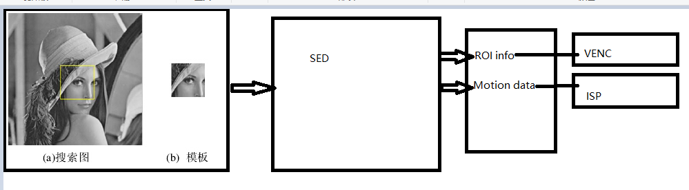
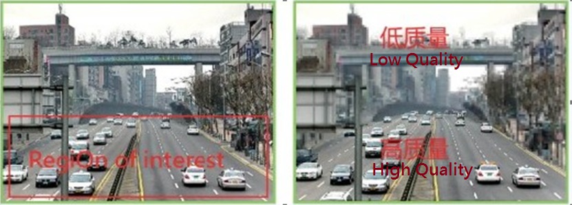
Through the intelligent identification of ROI by the SED, as well as the dynamic setting of QP value against the ROI designated by the image, we can effectively reduce bandwidth while ensuring the quality of the image.
Note
SAD functions are integrated into VENC AVBR mode starting from platform Muffin, that is, the encoder integrates the SAD calculation function inside, and the SED module is no longer needed to help calculate the SAD.
1.1.1. Image Detection Algorithms Type
-
E_MI_IVEOBJDETECT_ALGOPARAM: detects moving objects based on VDF/MD mode, with support for ROI image tracking.
-
E_MI_CNNOBJDETECT_ALGOPARAM: objects which this algorithm can detect include bicycle, bus, car, motorbike, human beings. ROI image tracking is supported.
-
E_MI_MOTIONDETECT_ALGOPARAM: motion detection based on IVE, supported only for AVBR motion detection.
The above three detection algorithms can be supported simultaneously by creating different detection channel instances.
1.1.2. Role of SED
The SED is responsible for identifying ROI and motion information using Sigmastar or third-party intelligent algorithms. ROI information is used for VENC setting, and motion information is used for automatic adjustment of ISP sharpness, etc.
1.1.3. Data Sources for SED
SED obtains yuv data through through SCL for intelligent detection (the resolution of yuv input is 352*288).
1.1.4. SED Detection Flow

1.1.5. Platform Limitations
Human non-vehicle detection is based on the detection of AI training model through IPU. The accuracy of specific detection depends on the accuracy of AI model training. Currently, only the Pudding platform support human non-vehicle detection, while other low-order platforms do not.
1.2. Keyword Description
-
VDF
VDF (Video Detection Framework) realizes initialization of MD, OD and VG video channels, channel management, management of video detection results, channel destruction and other functions
-
IVE
IVE (Intelligent Video Engine) module is responsible for the processing and calculation of image data. The SAD value of two images can be obtained through MI_IVE_Sad, and the histogram statistical task data can be executed through MI_IVE_Hist to achieve the dynamic and static detection of images.
-
IPU
IPU (AI Process Unit) is an AI model processing and computing unit. The MI IPU module implements the rapid reasoning function of the network model, independently configuring the network model for each channel, and managing the acquisition and release of input and output data.
-
ROI
ROI (Region Of Interest) means coding against region of interest. With the ROI function enabled, important or mobile area, i.e. the ROI region, will be in high quality lossless coding. On the other ahnd, for those areas which remain motionless or which are not selected as the ROI areas, the bit rate and image quality will be reduced for standard definition video compression, or even omission of this part of video transmission, so as to ultimately save the network bandwidth and video storage space. Users can configure their ROI area to limit the area of image Qp, so as to differentiate the Qp of that area from the Qp of the other area in the image. The system supports both H.264 and H.265 encoding ROI settings and provides 16 ROI regions for simultaneous use by users.
The 16 ROI regions can overlap with one another, and the priority of the overlapped regions is increased in sequence according to the index number of 0-15, that is to say, the QP of the overlapped regions is finally determined to be processed only according to the highest priority regions. The ROI area can be configured with absolute QP and relative QP.
Absolute QP: The QP in ROI area is the QP value set by the user
Relative QP: The QP in ROI area is the sum of the QP generated by rate control and the QP offset value set by the user. In the following example, the encoded image adopts the FixQp mode, with the image QP set to 30, that is, the QP value of all macroblocks of the image is 30. ROI region 0 is set to absolute QP mode, with QP value = 20, index = 0; ROI region 1 is set to relative QP mode, with QP value = -15, index = 1. Because the index of ROI region 0 is smaller than the index of ROI region 1, the QP of ROI region 1 with higher priority is set in the overlapped image region. The QP value of region 1 is 30-15 = 15, whereas the the QP value of region 0 is 20.

-
Motion
SAD information that contains the image.
-
QP
QP (Quantization Parameter) value corresponds to the sequence number of quantized step length. The smaller the value, the smaller the quantized step length, the higher the quantization accuracy, the better the picture quality, and the larger the size encoded.
-
MD
Motion detection is used to detect the movement of objects in films, and is applied to security monitoring in actual application.
-
OD
The occlusion detection is used to detect whether the received movie is blocked and to output the blocked detection result, if any.
-
VG
The virtual line segment is used to detect whether an object has crossed the set alarm line.
A zone intrusion is used to detect if an object is passing through a set alarm area.
-
SAD
SAD means the Sum of Absolute Differences. This algorithm is often used for image block matching – the sum of the absolute value of the difference between the corresponding values of each pixel is used to evaluate the similarity of two image blocks. It can be seen that this algorithm is fast, but not accurate, and is usually used for preliminary screening of multistage processing.
The value range of SAD is [0, 255]. All SAD values are divided into 16 ranges:
[0, 10), [10, 15, 15, 20), [20, 25), [25, 30), 30, 40), [40, 50), 50, 60), [; seven), 60, 70), [80 living), (90100), (100120), (120140), (140160), [160, 255].
In this algorithm, the percentage of all MB (8*8) in a frame that falls into the above range is calculated.
The larger the value, the more static the picture.
-
CBR
CBR refers to Constant Bit Rate in case of Motion. Since the code rate is constant, the size of the code word can only be reduced by increasing QP, which will however cause the image quality to worsen. When the scene is still, the image quality becomes better; therefore, the image quality is generally unstable. This algorithm prioritizes bitrate (bandwidth) over other factors.
-
VBR
VBR (Variable Bit Rate) means the bit rate is dynamic, varying with the complexity of the image, so its coding efficiency is relatively high. When motion occurs, mosaic is rare. The bitrate control algorithm determines the bit rate to be used according to the image content. If the image content is simple, less bitrate will be allocated (it seems that the codeword is more suitable), and if the image content is complex, more codeword will be allocated, which not only guarantees the quality but also takes into account the bandwidth limit. This algorithm gives priority to image quality over other factors.
-
CVBR
CVBR (Constrained VariableBit Rate) is an improvement on VBR. The Maximum bitRate or Average bitRate corresponding to this algorithm is constant. This method maintains the advantages of the above two methods: when the image content is still, the bandwidth is saved; when the image content is in motion, the bandwidth saved in the early stage is used to improve the image quality as much as possible, so as to achieve the purpose of retaining both bandwidth and image quality. This method usually allows the user to input the maximum and minimum bit rate. When still, the bit rate will be kept at the minimum bit rate, and when in motion, the bit rate will be greater than the minimum bit rate, but not more than the maximum bit rate.
-
ABR
The ABR (Average Bit Rate) refers to the average bit rate to reach the set code rate in a certain time range. The local peak code rate can exceed the set code rate, but the average code rate is constant.
-
AVBR
AVBR (Adaptive Variable Bit Rate) variable bit rate, which allows the code rate to fluctuate during the code rate statistical time, so as to ensure the stable quality of the coded image. The code rate control internally detects the motion and static state of the current scene, encodes with a higher code rate when moving, and actively reduces the target code rate when it is stationary.
Taking H.264 encoding as an example, the VENC module provides users with settings for MaxBitrate, ChangePos and MinStillPercent. MaxBitrate represents the maximum bit rate in a sports scene, and MaxBitrate*ChangePos*MinStillPercent represents the minimum bit rate in a static situation.
The target bit rate will be adjusted between the maximum bit rate and the minimum bit rate according to the degree of movement. MaxQp and MinQp are used to control the quality range of the image. The bit rate control takes QP clamping as the highest priority. If it exceeds MinQp, the bit rate control will be invalid in the MaxQp range.
-
IOU
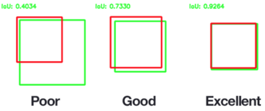
The IOU (Intersection over Union) concept, used in target detection, means the overlapping rate of the generated candidate bound and the original ground truth bound, that is, the ratio of their intersection and union.
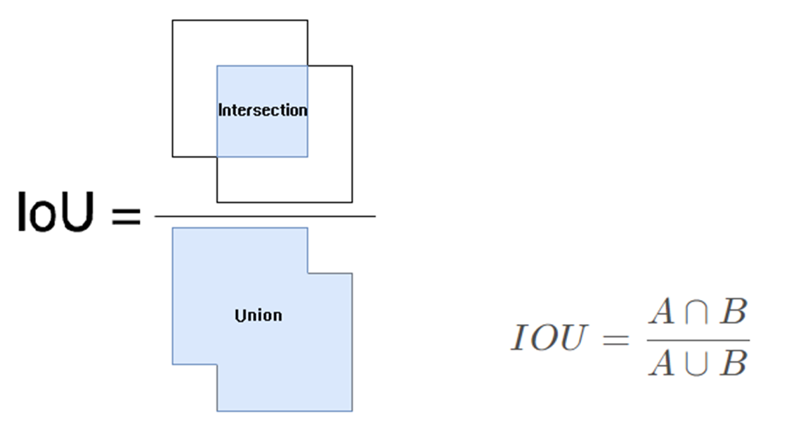
The best case is complete overlap, i.e. the ratio is 1.
2. API List
This module provides the following APIs:
| API Name | Function |
|---|---|
| MI_SED_CreateChn | Create an SED channel |
| MI_SED_DestroyChn | Destroy an SED channel |
| MI_SED_StartDetector | Start detection of designated channel |
| MI_SED_StopDetector | Stop detection of designated channel |
| MI_SED_AttachToVencChn | Attach module to designated venc channel |
| MI_SED_DetachFromVencChn | Detach module from designated venc channel |
| MI_SED_GetRect | Get the rect info data detected by SED |
| MI_SED_SetDbgLevel | Set SED module debug level, control log output |
2.1. MI_SED_CreateChn
-
Function
Create an SED channel
-
Syntax
MI_S32 MI_SED_CreateChn(MI_SED_CHN SedChn,
MI_SED_DetectorAttr_t* pstAttr);
-
Parameter
Parameter Name Description Input/Output SedChn SED channel number. Range: [0, SED_MAX_CHN_NUM) Input pstAttr SED detection attribute pointer Input -
Return Value
-
Zero: Successful
-
Non-zero: Failed, see error code for details
-
-
Dependency
-
Header: mi_common.h, mi_sed.h
-
Library: libmi_sed.a
-
2.2. MI_SED_DestroyChn
-
Function
Destroy an SED channel.
-
Syntax
MI_S32 MI_SED_DestroyChn(MI_SED_CHN SedChn);
-
Parameter
Parameter Name Description Input/Output SedChn SED channel number. Range:[0, SED_MAX_CHN_NUM) Input -
Return Value
-
Zero: Successful
-
Non-zero: Failed, see error code for details
-
-
Dependency
-
Header: mi_common.h, mi_sed.h
-
Library: libmi_sed.a
-
2.3. MI_SED_StartDetector
-
Function
Start detection of a designated channel.
-
Syntax
MI_S32 MI_SED_StartDetector(MI_SED_CHN SedChn);
-
Parameter
Parameter Name Description Input/Output SedChn SED channel number. Range:[0, SED_MAX_CHN_NUM) Input -
Return Value
-
Zero: Successful
-
Non-zero: Failed, see error code for details
-
-
Dependency
-
Header: mi_common.h, mi_sed.h
-
Library: libmi_sed.a
-
2.4. MI_SED_StopDetector
-
Function
Stop detection of a designated channel.
-
Syntax
MI_S32 MI_SED_StopDetector(MI_SED_CHN SedChn);
-
Parameter
Parameter Name Description Input/Output SedChn SED channel number. Range:[0, SED_MAX_CHN_NUM) Input -
Return Value
-
Zero: Successful
-
Non-zero: Failed, see error code for details
-
-
Dependency
-
Header: mi_common.h, mi_sed.h
-
Library: libmi_sed.a
-
2.5. MI_SED_AttachToVencChn
-
Description
Attach module to designated venc channel.
-
Syntax
MI_S32 MI_SED_AttachToChn(MI_SED_CHN SedChn,
MI_SED_TARGET_CHN TargetChn);
-
Parameter
Parameter Name Description Input/Output SedChn SED channel number. Range:[0, SED_MAX_CHN_NUM) Input TargetChn Target encoder channel. Range:[0,VENC_MAX_CHN_NUM) Input -
Return Value
-
Zero: Successful
-
Non-zero: Failed, see error code for details
-
-
Dependency
-
Header: mi_common.h, mi_sed.h
-
Library: libmi_sed.a
-
2.6. MI_SED_DetachFromVencChn
-
Description
Detach module from designated venc channel.
-
Syntax
MI_S32 MI_SED_DetachFromChn(MI_SED_CHN SedChn,
MI_SED_TARGET_CHN TargetChn);
-
Parameter
Parameter Name Description Input/Output SedChn SED channel number. Range:[0, SED_MAX_CHN_NUM) Input TargetChn Target encoder channel. Range:[0,VENC_MAX_CHN_NUM) Input -
Return Value
-
Zero: Successful
-
Non-zero: Failed, see error code for details
-
-
Dependency
-
Header: mi_common.h, mi_sed.h
-
Library: libmi_sed.a
-
2.7. MI_SED_GetRect
-
Description
Get the rect info data detected by sed
-
Syntax
MI_S32 MI_SED_GetRect(MI_SED_CHN SedChn, MI_SED_RectInfo_t
*pstRectInfo)
-
Parameter
Parameter Name Description Input/Output SedChn SED channel number. Range:[0, SED_MAX_CHN_NUM) Input pstRectInfo Rect info Output -
Return Value
-
Zero: Successful
-
Non-zero: Failed, see error code for details
-
-
Dependency
-
Header: mi_common.h, mi_sed.h
-
Library: libmi_sed.a
-
2.8. MI_SED_SetDbgLevel
-
Description
Set SED module debug level, control log output
-
Syntax
MI_S32 MI_SED_SetDbgLevel(MI_DBG_LEVEL_e eLevel)
-
Parameter
Parameter Name Description Input/Output eLevel MI debug level enum. Range:[0, MI_DBG_ALL] Input -
Return Value
-
Zero: Successful
-
Non-zero: Failed, see error code for details
-
-
Dependency
-
Header: mi_common.h, mi_sed.h
-
Library: libmi_sed.a
-
3. SED Data Type
The relevant data types and data structures are defined as follows:
| Data type | Definition |
|---|---|
| SED_MAX_CHN_NUM | Define maximum SED channel number |
| SED_MAX_ROI_NUM_PER_CHN | Define maximum ROI number per channel |
| SED_MAX_TARGET_CHN_NUM_PER_CHN | Define maximum target VENC channel number per SED channel |
| SED_MAX_CUS_DEF_ALGOPARAM_NUM | Define maximum number of supported customer-defined algorithm |
| MI_SED_CHN | Define SED channel number |
| MI_SED_TARGET_CHN | Define VENC encoder channel number corresponding to the SED channel number |
| MI_SED_AlgoType_e | Define SED algorithm type |
| MI_SED_InputAttr_t | Define SED input attribute |
| MI_SED_IveObjDetect_Algo_t | Do IVE Detector Param |
| MI_SED_CNNObjDetect_Algo_t | Do CNN Object Detect Param |
| MI_SED_MontionObjDetect_Algo_t | Define SED input attribute |
| MI_SED_Rect_t | Get SED detector rect data |
| MI_SED_RectInfo_t | All rectangles info detected by SED |
| MI_SED_AlgoAttr_t | Define SED algorithm properties |
| MI_SED_TargetAttr_t | Define the final effective coding target attribute |
| MI_SED_DetectorAttr_t | Define SED detection properties |
3.1. SED_MAX_CHN_NUM
-
Description
Define maximum SED channel number.
-
Definition
#define SED_MAX_CHN_NUM (4)
3.2. SED_MAX_ROI_NUM_PER_CHN
-
Description
Define maximum ROI number per channel.
-
Definition
#define SED_MAX_ROI_NUM_PER_CHN (16)
3.3. SED_MAX_TARGET_CHN_NUM_PER_CHN
-
Description
Define maximum target VENC channel number per SED channel.
-
Definition
#define SED_MAX_TARGET_CHN_NUM_PER_CHN (8)
3.4. SED_MAX_CUS_DEF_ALGOPARAM_NUM
-
Description
Define maximum number of supported customer-defined algorithm.
-
Definition
#define SED_MAX_CUS_DEF_ALGOPARAM_NUM (10)
3.5. MI_SED_CHN
-
Description
Define SED channel number.
-
Definition
typedef MI_S32 MI_SED_CHN;
3.6. MI_SED_TARGET_CHN
-
Description
Define VENC encoder channel number corresponding to the SED channel number.
-
Definition
typedef MI_S32 MI_SED_TARGET_CHN;
3.7. MI_SED_AlgoType_e
-
Description
Define SED algorithm type.
-
Definition
typedef enum { E_MI_DEFAULT_ALGOPARAM = 0x0, E_MI_CUSDEF_ALGOPARAM = 0x1, E_MI_DEFAULT_ALGOPARAM_MAX } MI_SED_AlgoType_e; -
Member
Member Name Description E_MI_DEFAULT_ALGOPARAM Use default SDK algorithm E_MI_CUSDEF_ALGOPARAM Use customer-defined algorithm.
3.8. MI_SED_InputAttr_t
-
Description
Define SED input attribute.
-
Definition
typedef struct MI_SED_InputAttr_s { MI_U32 u32Width; MI_U32 u32Height; MI_U32 u32FrameRateNum; MI_U32 u32FrameRateDen; MI_SYS_ChnPort_t stInputPort; } MI_SED_InputAttr_t; -
Member
Member Name Description u32Width Input YUV width u32Height Input YUV height u32FrameRateNum Input YUV framerate numerator u32FrameRateDen Input YUV framerate denominator stInputPort Input YUV channel attribute -
Related Data Type and Interface
3.9. MI_SED_IveObjDetect_Algo_t
-
Description
Do IVE Detector Param
-
Definition
typedef struct MI_SED_IveObjDetect_Algo_s

MI_U32 u32VdfChn;

MI_U8 u8Sensitivity;

} MI_SED_IveObjDetect_Algo_t;
-
Member
Member Name Description u32VdfChn Vdf channel number u8Sensitivity Algorithm sensitivity
3.10. MI_SED_CNNObjDetect_Algo_t
-
Description
Do CNN Object Detect Param
-
Definition
typedef struct MI_SED_CNNObjDetect_Algo_s { MI_U32 u32MaxVariableBufSize; MI_U32 u32IPUChnId; MI_U8 *u8FwImagePath; MI_U8 *u8ModelImagePath; } MI_SED_CNNObjDetect_Algo_t; -
Member
Member Name Description u32MaxVariableBufSize Maximum memory required by IPU algorithm u32IPUChnId IPU Channel Number u8FwImagePath IPU firmeware file path u8ModelImagePath AI Model file path
3.11. MI_SED_MontionObjDetect_Algo_t
-
Description
Define SED input attribute.
-
Definition
typedef struct MI_SED_InputAttr_s { MI_IVE_HANDLE iveHandle; } MI_SED_InputAttr_t; -
Member
Member Name Description iveHandle IVE file handle, defult value is 0
3.12. MI_SED_Rect_t
-
Description
Get SED detector rect data
-
Definition
typedef struct MI_SED_Rect_s { MI_U32 u32Left; MI_U32 u32Top; MI_U32 u32Width; MI_U32 u32Height; } MI_SED_Rect_t; -
Member
Member Name Description u32Left Column coordinates of the upper left corner of the rectangle u32Top Row coordinates of the upper left corner of the rectangle u32Width Width of rectangle u32Height Height of rectangle
3.13. MI_SED_RectInfo_t
-
Description
All rectangle info detected by SED
-
Definition
typedef struct MI_SED_RectInfo_s { MI_U32 u32RectCount; MI_SED_Rect_t stRect[SED_MAX_ROI_NUM_PER_CHN]; } MI_SED_RectInfo_t; -
Member
Member Name Description u32RectCount Number of rectangles stRect Information of rectangular box
3.14. MI_SED_AlgoAttr_t
-
Description
Define SED algorithm properties
-
Definition
typedef struct MI_SED_CusAlgoAttr_ s { MI_SED_AlgoType_e eType; Union { MI_SED_IveObjDetect_Algo_t stIveObjDetectAlgo; MI_SED_CNNObjDetect_Algo_t stCNNObjDetectAlgo; MI_SED_MotionObjDetect_Algo_t stMotionObjDetectAlgo; }; } MI_SED_AlgoAttr_t; -
Member
Member Name Description eType Type of algorithm used by SED stIveObjDetectAlgo IVE algorithm parameters stCNNObjDetectAlgo CNN algorithm parameters stMotionObjDetectAlgo Motion algorithm parameters
3.15. MI_SED_TargetAttr_t
-
Description
Define the final effective coding target attribute
-
Definition
typedef struct MI_SED_TargetAttr_s { MI_S32 s32RltQp; } MI_SED_TargetAttr_t; -
Member
Member Name Description s32RltQp ROI relative QP value
3.16. MI_SED_DetectorAttr_t
-
Description
Define SED detection properties
-
Definition
typedef struct MI_SED_DetectorAttr_s { MI_SED_InputAttr_t stInputAttr; MI_SED_AlgoAttr_t stAlgoAttr; MI_SED_TargetAttr_t stTargetAttr; } MI_SED_DetectorAttr_t; -
Member
Member Name Description stInputAttr Properties of the SED input section stAlgoAttr Attributes related to SED algorithm stTargetAttr Target control attribute of SED final effect
4. Error Code
The SED API error codes are shown in the table below:
| Error Code | Macro Definition | Description |
|---|---|---|
| 0x00000000 | MI_SUCCESS | Success |
| 0xA01E2002 | MI_ERR_SED_INVALID_CHNID | Invalid channel ID |
| 0xA01E2003 | MI_ERR_SED_ILLEGAL_PARAM | At lease one parameter is illegal |
| 0xA01E2004 | MI_ERR_SED_EXIST | Channel already exists |
| 0xA01E2005 | MI_ERR_SED_UNEXIST | Channel does not exist |
| 0xA01E2006 | MI_ERR_SED_NULL_PTR | Using a NULL point |
| 0xA01E200c | MI_ERR_SED_NOMEM | Failure caused by malloc memory |
| 0xA01E2013 | MI_ERR_SED_CHN_NOT_STARTED | Channel not started |
| 0xA01E2014 | MI_ERR_SED_CHN_NOT_STOPPED | Channel not stopped |
| 0xA01E2017 | MI_ERR_SED_NOT_ENABLE | Channel not enabled |
5. Demo
Build Demo code:
cd sdk/verify/mi_demo/alderaan$
make
Generated executable program in sdk\verify\mi_demo\out\demo\app\prog_sed.