MI LDC API
REVISION HISTORY
| Revision No. | Description |
Date |
|---|---|---|
| 3.0 | 12/04/2020 | |
| 3.1 | 07/04/2021 | |
| 08/25/2021 | ||
| 3.2 | 04/01/2022 |
1. OVERVIEW
1.1. Module Description
LDC (Lens Distortion Correction), support Lens Distortion Correction、Image Stitch 、Blending、Digital Image Stabilization (DIS) and Lookup Table Feature (LUT).
1.2. Flow Chart
1.2.1. Tiramisu

Note:
-
32X2 and 16X2 are the width and height alignment limits of the input image and the output image.
-
Tiramisu, Muffin and Mochi use the same flow chart.
1.2.2. Maruko

Note:
-
On Platform Maruko, LDC is an ISP submodule and is actually input and output by the ISP.
-
On Platform Maruko, there is only one LDC device, and each device supports the same number of channels as the ISP.
-
The width and height alignment of the input image is limited to 8x2, scaling is not supported, and the output width and height is the same as the input width and height.
1.3. Platform Features
Functions supported in different platforms:
Device 0:
| Feature Platform |
LDC | Stitch and Blending | DIS | LUT |
|---|---|---|---|---|
| Tiramisu | Y | Y | Y | N |
| Muffin | Y | Y | Y | Y |
| Mochi | Y | Y | Y | Y |
| Maruko | Y (Horizontal) | N | N | N |
Device 1:
| Feature Platform |
LDC | Stitch and Blending | DIS | LUT |
|---|---|---|---|---|
| Muffin | Y | Y | Y | Y |
Features:
-
Lens distortion correction
According to lens calibration parameters, input image is subjected to distortion correction processing, and then output according to the projection mode and the region of interest configured by the user.
-
Image stitching and fusion
Distortion correction is performed on images come from multiple sensors, then multiple images are stitched together, and finally the overlapping areas of the images are fused.
-
Digital image stabilization
Currently supports anti-shake algorithm with groscope, that is, calculate the movement offset of the image of the current frame according to the data generated by the gyroscope, and then according to the motion offset condition performs translation, rotation and other transformations on the current image, so as to achieve the effect of anti-shake.
-
Lookup table
Provides a two-dimensional lookup table function. The data bit width of the index and table in the x and y directions are both 8bit, which can be used for fast search of the weight table of the image fusion algorithm.
1.4. Keyword
-
device
Ldc corresponding hardware device
-
channel
The LDC module processes channels, and the LDC hardware of each channel is time-sharing multiplexed.
2. API LIST
This module provides the following APIs:
| API Name | Function |
|---|---|
| MI_LDC_CreateDevice | Create an LDC device |
| MI_LDC_DestroyDevice | Destroy an LDC device |
| MI_LDC_CreateChannel | Create an LDC channel |
| MI_LDC_DestroyChannel | Destroy an LDC channel |
| MI_LDC_StartChannel | Start an LDC channel |
| MI_LDC_StopChannel | Stop an LDC channel |
| MI_LDC_GetOutputPortAttr | Get the LDC output attribute |
| MI_LDC_SetChnParam | Set the LDC channel attribute |
| MI_LDC_DoLutDirectTask | Execute table lookup tasks and send buffer directly to ldc hardware for processing |
| MI_LDC_SetOutputPortAttr | Configure LDC output attribute |
| MI_LDC_AttachToChn | Attach Ldc Channel to corresponding module channel |
| MI_LDC_DetachFromChn | Detach Ldc Channel |
2.1. MI_LDC_CreateDevice
-
Description
Create an LDC device
-
Syntax
MI_S32 MI_LDC_CreateDevice(MI_LDC_DEV devId, MI_LDC_DevAttr_t *pstDevAttr);
-
Parameters
Parameter Name Description Input/Output devId Device ID number Input pstDevAttr eWorkMdoe Device working mode attribute Input -
Return Value
-
Zero: Successful
-
Non-zero: Failed, see ERROR CODE for details.
-
-
Dependence
-
Header file: mi_ldc.h
-
Lib: libmi_ldc.a
-
-
Note
Currently only devId = 0 is supported.
-
Example
LDC initialization settings and exit example:
Tiramisu, Muffin, Mochi Platform:
MI_S32 s32Ret = MI_SUCCESS;
MI_LDC_DEV LdcDevId = 0;
MI_LDC_CHN LdcChnId = 0;
MI_LDC_DevAttr_t stDevAttr = {0};
MI_LDC_ChnAttr_t stChnAttr = {};
MI_LDC_SensorCalibInfo_t * pstCalibInfo = &stChnAttr.stCalibInfo;

stChnAttr. eMode = MI_LDC_WORKMODE_LDC ;
s32Ret = ReadBufFromFile("ldc.json", stChnAttr. pConfigAddr, stChnAttr.u32ConfigSize);
if (s32Ret)
{
    return s32Ret;
}

stChnAttr.eInfoType = MI_LDC_MAPINFOTYPE_SENSORCALIB;
s32Ret = ReadBufFromFile("CalibPoly.bin", pstCalibInfo.pCalibPolyBinAddr, pstCalibInfo.u32CalibPolyBinSize);
if (s32Ret)
{
    return s32Ret;
}

MI_LDC_CreateDevice(LdcDevId, &stDevAttr);
MI_LDC_CreateChannel(LdcDevId, LdcChnId, &stChnAttr);
MI_LDC_StartChannel(LdcDevId, LdcChnId);

ReleaseBuf(stChnAttr. pConfigAddr);
ReleaseBuf(pstCalibInfo.pCalibPolyBinAddr);

/*Destroy channel*/
MI_LDC_StopChannel(LdcDevId, LdcChnId);
MI_LDC_DestroyChannel(LdcDevId, LdcChnId);
MI_LDC_DestroyDevice(LdcDevId);
Maruko Platform:
MI_S32 s32Ret = MI_SUCCESS; MI_LDC_DEV LdcDevId = 0; MI_LDC_CHN LdcChnId = 0; MI_LDC_DevAttr_t stDevAttr = {0}; MI_LDC_ChnAttr_t stChnAttr = {}; MI_SYS_ChnPort_t stDstChnPort = {}; stChnAttr. eMode = MI_LDC_WORKMODE_LDC ; s32Ret = ReadBufFromFile("ldc.json", stChnAttr. pConfigAddr, stChnAttr.u32ConfigSize); if (s32Ret) { return s32Ret; } stDstChnPort. eModId = E_MI_MODULE_ID_ISP; stDstChnPort. u32DevId = 0; stDstChnPort. u32ChnId = 0; stDstChnPort. u32PortId = 0; MI_LDC_CreateDevice(LdcDevId, &stDevAttr); MI_LDC_CreateChannel(LdcDevId, LdcChnId, &stChnAttr); MI_LDC_AttachToChn(LdcDevId, LdcChnId, &stDstChnPort); /*Exit and release buffer*/ ReleaseBuf(stChnAttr. pConfigAddr); MI_LDC_DetachFromChn(LdcDevId, LdcChnId, &stDstChnPort); MI_LDC_DestroyChannel(LdcDevId, LdcChnId); MI_LDC_DestroyDevice(LdcDevId); -
Related APIs
2.2. MI_LDC_DestroyDevice
-
Description
Destroy an LDC device
-
Syntax
MI_S32 MI_LDC_DestroyDevice(MI_LDC_DEV devId);
-
Parameters
Parameter Name Description Input/Output devId Device ID number Input -
Return Value
-
Zero: Successful
-
Non-zero: Failed, see ERROR CODE for details.
-
-
Dependence
-
Header file: mi_ldc.h
-
Lib: libmi_ldc.a
-
-
Note
Currently only devId = 0 is supported.
-
Example
Refer to MI_LDC_CreateDevice example.
-
Related APIs
2.3. MI_LDC_CreateChannel
-
Description
Create an LDC channel
-
Syntax
MI_S32 MI_LDC_CreateChannel(MI_LDC_DEV devId, MI_LDC_CHN chnId,
MI_LDC_ChnAttr_t *pstChnAttr);
-
Parameters
Parameter Name Description Input/Output devId Device ID number Input chnId LDC Channel number Input -
Return Value
-
Zero: Successful
-
Non-zero: Failed, see ERROR CODE for details.
-
-
Dependence
-
Header file: mi_ldc.h
-
Lib: libmi_ldc.a
-
-
Note
This API needs to be called after MI_LDC_CreateDevice.
-
Example
Refer to MI_LDC_CreateDevice example.
-
Related APIs
2.4. MI_LDC_DestroyChannel
-
Description
Destroy an LDC channel
-
Syntax
MI_S32 MI_LDC_DestroyChannel(MI_LDC_DEV devId, MI_LDC_CHN chnId);
-
Parameters
Parameter Name Description Input/Output devId Device ID number Input chnId LDC Channel number Input -
Return Value
-
Zero: Successful
-
Non-zero: Failed, see ERROR CODE for details.
-
-
Dependence
-
Header file: mi_ldc.h
-
Lib: libmi_ldc.a
-
-
Example
Refer to MI_LDC_CreateDevice example.
-
Related APIs
2.5. MI_LDC_StartChannel
-
Description
Start an LDC channel.
-
Syntax
MI_S32 MI_LDC_StartChannel(MI_LDC_DEV devId, MI_LDC_CHN chnId);
-
Parameters
Parameter Name Description Input/Output devId Device ID number Input chnId LDC Channel number Input -
Return Value
-
Zero: Successful
-
Non-zero: Failed, see ERROR CODE for details.
-
-
Dependence
-
Header file: mi_ldc.h
-
Lib: libmi_ldc.a
-
-
Note
-
Call this API after Device and Channel have been created.
-
Platform Maruko does not support this interface. Use MI_LDC_AttachToChn instead.
-
-
Example
Refer to MI_LDC_CreateDevice example.
-
Related APIs
2.6. MI_LDC_StopChannel
-
Description
Stop an LDC channel.
-
Syntax
MI_S32 MI_LDC_StopChannel(MI_LDC_DEV devId, MI_LDC_CHN chnId);
-
Parameters
Parameter Name Description Input/Output devId Device ID number Input chnId LDC Channel number Input -
Return Value
-
Zero: Successful
-
Non-zero: Failed, see ERROR CODE for details.
-
-
Dependence
-
Header file: mi_ldc.h
-
Lib: libmi_ldc.a
-
-
Note
- Platform Maruko does not support this interface. Use MI_LDC_AttachToChn instead.
-
Example
Refer to MI_LDC_CreateDevice example.
-
Related APIs
2.7. MI_LDC_GetOutputPortAttr
-
Description
Get the LDC output attribute.
-
Syntax
MI_S32 MI_LDC_GetOutputPortAttr(MI_LDC_DEV devId, MI_LDC_CHN chnId,
MI_LDC_OutputPortAttr_t *pstOutputAttr);
-
Parameters
Parameter Name Description Input/Output devId Device ID number Input chnId LDC Channel number Input pstOutputAttr Output attribute Output -
Return Value
-
Zero: Successful
-
Non-zero: Failed, see ERROR CODE for details.
-
-
Dependence
-
Header file: mi_ldc.h
-
Lib: libmi_ldc.a
-
-
Note
The output information is set in bin file. When the backend needs to know the input information, you can obtain the information through this interface.
-
Example
Refer to MI_LDC_CreateDevice example.
2.8. MI_LDC_SetChnParam
-
Description
Set the LDC channel attribute.
-
Syntax
MI_S32 MI_LDC_SetChnParam (MI_LDC_DEV devId, MI_LDC_CHN chnId,
MI_LDC_ChnParam_t *pstChnParam);
-
Parameters
Parameter Name Description Input/Output devId Device ID number Input chnId Channel number Input pstChnParam Channel configuration parameter Input -
Return Value
-
Zero: Successful
-
Non-zero: Failed, see ERROR CODE for details.
-
-
Dependence
-
Header file: mi_ldc.h
-
Lib: libmi_ldc.a
-
-
Note
- Need to be used after MI_LDC_CreateChannel.
-
Example
Used when updating channel configuration, switching algorithm mode and adjusting lens parameters.
MI_LDC_DEV devId = 0;
MI_LDC_CHN chnId = 0;
MI_LDC_ChnParam_t  stChnParam = {};
MI_LDC_SensorCalibInfo_t *pCalibInfo = &stChnParam.stCalibInfo;

s32Ret = ReadBufFromFile(“ldc.json”, &stChnParam. pConfigAddr, &stChnParam.u32ConfigSize);
if (s32Ret)
{
    return s32Ret;
}
s32Ret = ReadBufFromFile(“CalibPoly.bin”, &pstCalibInfo.pCalibPolyBinAddr, &pstCalibInfo.u32CalibPolyBinSize);
if (s32Ret)
{
    return s32Ret;
}

MI_LDC_SetChnParam(devId, chnId, & stChnParam);

ReleaseBuf(stChnParam. pConfigAddr);
ReleaseBuf(pstCalibInfo.pCalibPolyBinAddr);
2.9. MI_LDC_DoLutDirectTask
-
Description
Execute table lookup tasks and send buffer directly to ldc hardware for processing.
-
Syntax
MI_S32 MI_LDC_DoLutDirectTask(MI_LDC_DEV devID, MI_LDC_CHN chnId,
MI_LDC_LutTaskAttr_t *pstAttr);
-
Parameters
Parameter Name Description Input/Output devID Device initialization parameters Input pstAttr Table looking-up task configuration attribute Input/Output -
Return Value
-
Zero: Successful
-
Non-zero: Failed, see ERROR CODE for details.
-
-
Dependence
-
Header file: mi_ldc.h
-
Lib: libmi_ldc.a
-
-
Example
MI_S32 s32Ret = MI_SUCCESS;
MI_LDC_DEV devId = 0;
MI_LDC_CHN chnId = 0;
MI_LDC_LutTaskAttr_t  stLutTask = {};
MI_LDC_DirectBuf_t stTableX = {}, stTableY = {}, stTableWeight = {};
void *pVirTableX = NULL, *pVirTableY=NULL, *pVirTableWeight = NULL;

#define LUT_TABLE_Init(path, table, ppVir, w, h, __exit_func__)
do { \
table.ePixelFormat = E_MI_SYS_PIXEL_FRAME_I8; \
table.u32Width = w; \
table.u32Height = h; \
table.u32Stride[0] = w; \

    s32Ret = MI_SYS_MMa_Alloc(0, NULL, w*h, &table.phyAddr[0]); \
    if (s32Ret)
    {
        printf(“failed to malloc buf\n”);
        goto __exit_func__;
}
s32Ret = MI_SYS_Mmap(table.phyAddr[0], w*h, ppVir, false); \
if (s32Ret)
{
    printf(“failed to Mmap buf\n”);
    goto __exit_func__;
}
s32Ret = ReadBufFromFile(path, ppVir, w*h);
if (s32Ret)
{
    goto __exit_func__;
}
} while(0)

#define LUT_TABLE_Deinit(table, pVir)
do { \
    if (pVir)
    {
    MI_SYS_Munmap(pVir, table.u32Width * table.u32Height);
}
if (table.phyAddr[0])
{
    MI_SYS_MMA_Free(0, table.phyAddr[0]);
}
} while(0)

LUT_TABLE_Init(“1080p_tableX”, stTableX, & pVirTableX, 1920, 1080, __exit);
LUT_TABLE_Init(“1080p_tableY”, stTableY, & pVirTableY, 1920, 1080, __exit);
LUT_TABLE_Init(“1080p_tableWeight”, stTableWeight, &pVirTableWeight, 1920, 1080, __exit);

MI_LDC_DoLutDirectTask (devId, chnId, & stLutTask);

__exit:
LUT_TABLE_Deinit(stTableX, pVirTableX);
LUT_TABLE_Deinit(stTableY, pVirTableY);
LUT_TABLE_Deinit(stTableWeight, pVirTableWeight);
2.10. MI_LDC_SetOutputPortAttr
-
Description
Configure LDC output attributes.
-
Syntax
MI_S32 MI_LDC_SetOutputPortAttr(MI_LDC_DEV devId, MI_LDC_CHN chnId,
MI_LDC_OutputPortAttr_t *pstOutputAttr);
-
Parameters
Parameter Name Description Input/Output devId Device id Input chnId Ldc Channel num Input pstOutputAttr Output attribute Input -
Return Value
-
Zero: Successful
-
Non-zero: Failed, see ERROR CODE for details.
-
-
Dependence
-
Header file: mi_ldc.h
-
Lib: libmi_ldc.a
-
-
Note
-
Used it after the channel is created (MI_LDC_CreateChannel).
-
Only support to configure the format outputted by LDC, supported formats: NV12, ARGB8888, BGRA8888.
-
Tiramisu and Maruko do not support this interface.
-
-
Example
MI_LDC_DEV devId = 0;
MI_LDC_CHN chnId = 0;
MI_LDC_OutputPortAttr_t  stLdcPortAttr = {};

MI_LDC_GetOutputPortAttr(devId, chnId, &stLdcPortAttr);
stLdcPortAttr.ePixelFmt = E_MI_SYS_PIXEL_FRAME_ARGB8888;
MI_LDC_SetOutputPortAttr(devId, chnId, &stLdcPortAttr);
2.11. MI_LDC_AttachToChn
-
Description
Attach Ldc Channel to corresponding module channel.
-
Syntax
MI_S32 MI_LDC_AttachToChn(MI_LDC_DEV devId, MI_LDC_CHN chnId, MI_SYS_ChnPort_t *pstChnPort);
-
Parameters
Parameter Name Description Input/Output devId Device id Input chnId Ldc channel id Input pstChnPort Channel port to be bound Input -
Return Value
-
Zero: Successful
-
Non-zero: Failed, see ERROR CODE for details.
-
-
Dependence
-
Header file: mi_ldc.h
-
Lib: libmi_ldc.a
-
-
Note
-
Used it after the channel is created (MI_LDC_CreateChannel).
-
Only binding ISP modules is supported.
-
-
Example
Refer to MI_LDC_CreateDevice example.
2.12. MI_LDC_DetachFromChn
-
Description
Detach Ldc Channel.
-
Syntax
MI_S32 MI_LDC_DetachFromChn(MI_LDC_DEV devId, MI_LDC_CHN chnId, MI_SYS_ChnPort_t *pstChnPort);
-
Parameters
Parameter Name Description Input/Output devId Device id Input chnId Ldc channel id Input pstChnPort Channel port to be bound Input -
Return Value
-
Zero: Successful
-
Non-zero: Failed, see ERROR CODE for details.
-
-
Dependence
-
Header file: mi_ldc.h
-
Lib: libmi_ldc.a
-
-
Example
Refer to MI_LDC_CreateDevice example.
3. LDC DATA TYPE
LDC module related data types are listed below:
| Data type | Definition |
|---|---|
| MI_LDC_DEV | Define LDC device type. |
| MI_LDC_CHN | Define LDC channel type. |
| MI_LDC_DevAttr_t | Define LDC device attribute. |
| MI_LDC_WorkMode_e | Define LDC work mode. |
| MI_LDC_MapInfoType_e | Define LDC mapping information type. |
| MI_LDC_DisplacementMapInfo_t | Define LDC displacement map information. |
| MI_LDC_SensorCalibInfo_t | Define LDC Sensor calibration information. |
| MI_LDC_ChnAttr_t | Define LDC channel attribute. |
| MI_LDC_ChnParam_t | Define LDC channel dynamic parameters. |
| MI_LDC_OutputPortAttr_t | Define LDC output port attribute. |
| MI_LDC_DirectBuf_t | Define LDC input buffer type. |
| MI_LDC_LutTaskAttr_t | Define LDC image lookup table task type. |
3.1. MI_LDC_DEV
-
Description
Define LDC device type
-
Definition
typedef MI_U32 MI_LDC_DEV;
3.2. MI_LDC_CHN
-
Description
Define LDC channel type
-
Definition
typedef MI_U32 MI_LDC_CHN;
3.3. MI_LDC_DevAttr_t
-
Description
LDC device initialization Parameters.
-
Definition
typedef struct MI_LDC_DevAttr_s { MI_U32 u32Reserved; } MI_LDC_DevAttr_t; -
Member
Member name Description u32Reserved Reserve -
Related Type
3.4. MI_LDC_WorkMode_e
-
Description
LDC working mode.
-
Definition
typedef enum { MI_LDC_WORKMODE_LDC = 0x01, MI_LDC_WORKMODE_LUT = 0x02, MI_LDC_WORKMODE_DIS_GYRO = 0x04, } MI_LDC_WorkMode_e; -
Member
Member name Description MI_LDC_WORKMODE_LDC LDC mode MI_LDC_WORKMODE_LUT LUT direct lookup mode MI_LDC_WORKMODE_DIS_GYRO DIS anti-shake mode based on gyroscope -
Related Type
3.5. MI_LDC_MapInfoType_e
-
Description
LDC mapping information type.
-
Definition
typedef enum { MI_LDC_MAPINFOTYPE_DISPMAP, MI_LDC_MAPINFOTYPE_SENSORCALIB, } MI_LDC_MapInfoType_e ; -
Member
Member name Description MI_LDC_MAPINFOTYPE_DISPMAP Displacement map MI_LDC_MAPINFOTYPE_SENSORCALIB sensor calibration information -
Related Type
3.6. MI_LDC_DisplacementMapInfo_t
-
Description
LDC displacement map information.
-
Definition
typedef struct MI_LDC_DisplacementMapInfo_s { void *pXmapAddr; void *pYmapAddr; MI_U32 u32XmapSize; MI_U32 u32YmapSize; } MI_LDC_DisplacementMapInfo_t; -
Member
Member name Description pXmapAddr The starting address of the X coordinate mapping table pYmapAddr The starting address of the Y coordinate mapping table u32XmapSize X coordinate mapping table size u32YmapSize Y coordinate mapping table size -
Related Type
3.7. MI_LDC_SensorCalibInfo_t
-
Description
LDC Sensor calibration information.
-
Definition
typedef struct MI_LDC_SensorCalibInfo_s { void *pCalibPolyBinAddr; MI_U32 u32CalibPolyBinSize; } MI_LDC_SensorCalibInfo_t; -
Member
Member name Description pCalibPolyBinAddr Calibration information pointer u32CalibPolyBinSize Calibration message size -
Related Type
3.8. MI_LDC_ChnAttr_t
-
Description
Channel attribute of LDC device.
-
Definition
typedef struct MI_LDC_ChnAttr_s { MI_LDC_WorkMode_e eMode; MI_BOOL bUseProjection3x3Matrix; MI_S32 as32Projection3x3Matrix[LDC_MAXTRIX_NUM]; MI_U16 u16UserSliceNum; MI_U16 u16FocalLength; void *pConfigAddr; MI_U32 u32ConfigSize; MI_LDC_MapInfoType_e eInfoType; union { MI_LDC_DisplacementMapInfo_t stDispMapInfo; MI_LDC_SensorCalibInfo_t stCalibInfo; }; } MI_LDC_ChnAttr_t; -
Member
Member name Description eMode Channel working mode bUseProjection3x3Matrix Indicates whether to use as32Projection3x3Matrix as32Projection3x3Matrix 3x3 Matrix information indicates the direction and position of the gyroscope (used in DIS mode) u16UserSliceNum The number of slices in the vertical direction, mainly used in the motion scene of the Rolling Shutter camera, each slice will have a separate 3x3 Matrix u16CropRatio The crop ratio of DIS output image.
For example, the input image is 1920x1080 and configure the crop ratio to 80, then the output image will be cropped (1-80%)/2 = 10%, the output image is 1536x864, which is the aligned image.u16FocalLength Focal length, unit: mm (used in DIS mode) pConfigAddr LDC configuration information address u32ConfigSize LDC configuration information size eInfoType LDC mapping information type stDispMapInfo/stCalibInfo LDC displacement table/sensor calibration information, includes distortion parameters -
Related Type
3.9. MI_LDC_ChnParam_t
-
Description
LDC device initialization parameters.
-
Definition
typedef struct MI_LDC_ChnParam_s { MI_BOOL bUseProjection3x3Matrix; MI_S32 as32Projection3x3Matrix[LDC_MAXTRIX_NUM]; MI_U16 u16FocalLength; void *pConfigAddr; MI_U32 u32ConfigSize; union { MI_LDC_DisplacementMapInfo_t stDispMapInfo; MI_LDC_SensorCalibInfo_t stCalibInfo; }; } MI_LDC_ChnParam_t; -
Member
Member name Description bUseProjection3x3Matrix Indicates whether to use as32Projection3x3Matrix as32Projection3x3Matrix 3x3 Matrix information indicates the direction and position of the gyroscope (used in DIS mode) u16FocalLength Focal length, unit: mm (used in DIS mode) pConfigAddr LDC configuration information address u32ConfigSize LDC configuration information size stDispMapInfo/ stCalibInfo LDC displacement table/sensor calibration information, includes distortion parameters -
Related Type
3.10. MI_LDC_OutputPortAttr_t
-
Description
Define LDC output port attribute
-
Definition
typedef struct MI_LDC_OutputPortAttr_s { MI_U16 u16Width; MI_U16 u16Height; MI_SYS_PixelFormat_e ePixelFmt; } MI_LDC_OutputPortAttr_t; -
Related Type
3.11. MI_LDC_DirectBuf_t
-
Description
LDC input buf type.
-
Definition
typedef struct MI_LDC_DirectBuf_s { MI_SYS_PixelFormat_e ePixelFormat; MI_U32 u32Width; MI_U32 u32Height; MI_U32 u32Stride[2]; MI_PHY phyAddr[2]; } MI_LDC_DirectBuf_t; -
Member
Member name Description ePixelFormat Image format u32Width Image width u32Height Image height u32Stride Image occupied bytes per line phyAddr Image storage physical address -
Related Type
3.12. MI_LDC_LutTaskAttr_t
-
Description
LDC image lookup table task type.
-
Definition
typedef struct MI_LDC_LutTaskAttr_s { struct MI_LDC_LutSrcBuf_s { MI_LDC_DirectBuf_t stTableX; MI_LDC_DirectBuf_t stTableY; MI_LDC_DirectBuf_t stTableWeight; } stSrcBuf; MI_LDC_DirectBuf_t stDstBuf; } MI_LDC_LutTaskAttr_t; -
Member
Member name Description stSrcBuf Table data source and weight lookup stDstBuf Store the output data after looking up -
Related Type
4. ERROR CODE
LDC API error code is defined in the table below:
| Error Code | Macro Definition | Description |
|---|---|---|
| 0xA0172001 | MI_ERR_LDC_INVALID_DEVID | Invalid device id |
| 0xA0172002 | MI_ERR_LDC_INVALID_CHNID | Invalid channel id |
| 0xA0172003 | MI_ERR_LDC_ILLEGAL_PARAM | Illegal Input argument |
| 0xA0172006 | MI_ERR_LDC_NULL_PTR | Illegal null pointer argument |
| 0xA0172008 | MI_ERR_LDC_NOT_SUPPORT | No support feature |
| 0xA017200C | MI_ERR_LDC_NOT_NOMEM | Not enough memory |
| 0xA0172012 | MI_ERR_LDC_BUSY | Channel is busy |
| 0xA0172015 | MI_ERR_LDC_MOD_NOT_INIT | Module is not inited |
| 0xA0172016 | MI_ERR_LDC_MOD_INITED | Module has been inited |
| 0xA0172018 | MI_ERR_LDC_PORT_NOT_DISABLE | Port is not be disable |
| 0xA017201F | MI_ERR_LDC_FAIL | Ldc failed to exec |
| 0xA0172300 | MI_ERR_LDC_DEV_CREATED | Device has been created |
| 0xA0172301 | MI_ERR_LDC_DEV_NOT_CREATE | Device has not been created |
| 0xA0172302 | MI_ERR_LDC_DEV_NOT_DESTROY | Device has not been destroyed |
| 0xA0172303 | MI_ERR_LDC_CHN_CREATED | Channel has been created |
| 0xA0172304 | MI_ERR_LDC_CHN_NOT_CREATE | Channel has not been created |
| 0xA0172305 | MI_ERR_LDC_CHN_NOT_STOP | Channel has not been stopped |
| 0xA0172306 | MI_ERR_LDC_CHN_NOT_DESTROY | Channel has not been destryoed |
| 0xA0172307 | MI_ERR_LDC_PORT_NOT_UNBIND | Port has not been unbinded |
5. PROCFS INTRODUCTION
5.1. cat
-
Debug info
# cat /proc/mi_modules/mi_ldc/mi_ldc0
-
Debug info analysis
Record LDC current usage status and relative attributes, which can be dynamically got for debug and test.
-
Parameter Description

Parameter Description Device Info
DevID Device ID IRQ_Enable IRQ enable state IsrCnt Count of interrupts, cmdq mode has no reference meaning IsrNum Interrupt number TotBlkNum Total number of ldc blocks that need to be processed FramDonCnt Number of processed frames cmdqif cmdq interface address HalInFrmCnt Total number of frames input to Hal HalDoneFrmCnt Total number of frames processed by Hal
HalDoneBlkCnt Total number of blocks processed by Hal HalIsrDoneCnt Number of Hal done interrupts HalIsrErrCnt Number of Hal Err interrupts 
Parameter Description Channel Info
ChnId Channel ID workmode Work mode of current channel status Status of current channel: 0:init 1:start 2:stop 3:destroyed InputWH Input frame resolution Pixel Input frame format Stride Input frame stride[0] InBufCnt The total number of frames input to the pre-level IntodoCnt The label of the frame to be processed (incremental) Atom The number of buffers held by the bottom layer EptzInit Time used to initialize the algorithm OneBinSz Time used to calculate the buffer size of the latest view OneBin Time used to calculate the latest view TotalBin Time used to calculate all views by LDC algorithm LdcDone LDC hardware processing time EnqTDeq Total time from getting the pre-level buf to processing it BlendT Alpha blending time 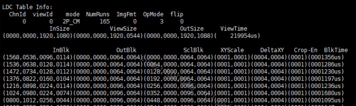
Parameter Description ChnId Channel ID ViewId Ldc corresponding Id mode Scene mode used by ldc NumRuns Total number of blocks that ldc current scene need to run ImgFmt Image format processed by ldc OpMode Current bbox mode:
0:2048x16 1:1024x32 2:512x64 3:256x128 4: 128x256flip Ldc mirror mode InSize The input area of the current view ViewSize The output area of the current view OutSize The output area of the current scene ViewTime Processing time of the current view Inblk The input area of the current blk OutBlk Algorithm output area of current blk SclBlk The output area of the current blk DeltaXY The coordinates of the current blk corresponding to the delta table BlkTime Corresponding to the processing time of blk
5.2. echo
Echo help view available commands:
# echo help > /proc/mi_modules/mi_ldc/mi_ldc0
| Function | Dump LDC output file |
|---|---|
| Command | echo writeoutfile [chnid cnt path] /proc/mi_modules/mi_ldc/mi_ldc0 |
| Parameter Description |
chnid: channel Id cnt: dump count path: dump path |
| Example | echo writeoutfile 0 2 /mnt/ /proc/mi_modules/mi_ldc/mi_ldc0 |
| Function | Dump LDC map file |
|---|---|
| Command | echo dumptablebin [chnid view/all path] /proc/mi_modules/mi_ldc/mi_ldc0 |
| Parameter Description |
chnid: channel id view/all(download mode), view: concrete viewed, all: all views of current scene path: dump path |
| Example | echo dumptablebin 0 all /mnt/ /proc/mi_modules/mi_ldc/mi_ldc0 |
| Function | Configure output properties |
|---|---|
| Command | echo setout[chnid width height pixel] /proc/mi_modules/mi_ldc/mi_ldc0 |
| Parameter Description |
chnid: channel id width: output image width height: output image height |
| Example | echo setout 0 1920 1080 11 /proc/mi_modules/mi_ldc/mi_ldc0 |
| Function | Loop the previous frame |
|---|---|
| Command | echo loopbuf [chnid cnt] /proc/mi_modules/mi_ldc/mi_ldc0 |
| Parameter Description |
chnid: channel id cnt: The number of times to loop the previous frame |
| Example | echo loopbuf 0 11 /proc/mi_modules/mi_ldc/mi_ldc0 |
| Function | Configure ldc internal debug trace |
|---|---|
| Command | echo debug [chnid str] /proc/mi_modules/mi_ldc/mi_ldc0 |
| Parameter Description |
chnid: channel id str(debug mode): off, ViewRes, ViewLock, ChnRdLock, ChnWrLock, DisGyro, Eptz |
| Example | echo debug 0 ChnRdLock /proc/mi_modules/mi_ldc/mi_ldc0 |
| Function | Configure a single ldc map |
|---|---|
| Command | echo setbin [chnid path] /proc/mi_modules/mi_ldc/mi_ldc0 |
| Parameter Description |
chnid: channel id path: map path |
| Example | echo setbin /mnt/ldc.bin /proc/mi_modules/mi_ldc/mi_ldc0 |